I2C 16bit ADC expansion for WC8

I think we need to change PLC to do single conversion, in that way, it gets more realistic reading.
Did you connected SCL and SDA properly? 
Try this program:
 
Code:
START    
	I2CWRITE 1 0 144 
	I2CWRITE 0 0 1 
	I2CWRITE 0 0 192 
	I2CWRITE 0 1 3 
	DELAY 50   
	I2CWRITE 1 0 144 
	I2CWRITE 0 1 0 
	I2CWRITE 1 0 145 
	I2CREAD 0 0 VAR1 
	I2CREAD 0 1 VAR2 
	DELAY 500   
END
 
because the reading result is 2's complement, -1 which is very close to 0 will be read as 65535 in my setup. see ADS1115 datasheet page 14
 
This chip configured at default scale (full scale 2.048V), then no input A0 will read zero
 
Code:
START    
	I2CWRITE 1 0 144 
	I2CWRITE 0 0 1 
	I2CWRITE 0 0 132 
	I2CWRITE 0 1 3 
	DELAY 500   
	I2CWRITE 1 0 144 
	I2CWRITE 0 1 0 
	I2CWRITE 1 0 145 
	I2CREAD 0 0 VAR1 
	I2CREAD 0 1 VAR2 
	DELAY 500   
END
 
This is the code read from channel A0 and put into analog AIP5.  You can make it a sub routine, and the command which channel and configuration into a byte and send to the subroutine.
 
Code:
START    
	I2CWRITE 1 0 144     # I2c start, write address for chip with addr connected to ground
	I2CWRITE 0 0 1       # configuration register address is 1
	I2CWRITE 0 0 132     # single end AINp = A0, full scale 2.048V, one shot conversion
	I2CWRITE 0 1 3       # disable comparator, 
	DELAY 500            # wait for conversion done, WC8 stop write to chip
	I2CWRITE 1 0 144     # I2c starts, write to chip on this I2c address
	I2CWRITE 0 1 0       # tell ADS1115 we address register 0, send STOP
	I2CWRITE 1 0 145     # I2c starts, tell chip we will read
	I2CREAD 0 0 RAM20    # reads first byte, notice ADS1115 require ACK, which is zero in ACK bit
	I2CREAD 0 1 RAM21    # reads 2nd byte, send stop to tell ADS1115 no more read
	SET VAR1 RAM2L       # display the two bytes value in VAR1
	MUL VAR1 3125 VAR2   # 3125 is the scale factor for 2.048 full scale reading
	DIV VAR2 1000000 AIP5   # divide by 1000000 to set value to 0.01V scale, store in AIP5
	DELAY 500   
END
 
CAI_Support said:
I use tftp flashed this board to 3.02.18b5, with above PLC code, it works fine.
thanks for this info, very much appreciated
 
CAI_Support said:
I2CWRITE 0 1 3 # disable comparator,


I2CREAD 0 0 RAM20 # reads first byte, notice ADS1115 require ACK, which is zero in ACK bit
I2CREAD 0 1 RAM21 # reads 2nd byte, send stop to tell ADS1115 no more read
SET VAR1 RAM2L # display the two bytes value in VAR1
regarding ' I2CWRITE 0 1 3 # disable comparator ', this also resets the timing to the slowest, 8 sps instead of the default 128 sps, which would make it

I2CWRITE 0 1 131

Did you need to slow the data rate down to get it working?
 

I tried this w/ no change.  yes my SCL & SDA are wired properly.

ANALOG:
    I2CWRITE 1 0 144
    I2CWRITE 0 0 1
    I2CWRITE 0 0 132
    I2CWRITE 0 1 3
    DELAY 500
    I2CWRITE 1 0 144
    I2CWRITE 0 1 0
    I2CWRITE 1 0 145   
    I2CREAD 0 0 RAM21
    I2CREAD 0 1 RAM20
    SET VAR2 RAM2L
    DELAY 500
    RET
 

with regard to the lower three lines in the quote, displaying the read bytes, my data sheet says

Second byte: the ADS1113/4/5 response with the
MSB of the Conversion register

Third byte: the ADS1113/4/5 response with the LSB
of the Conversion register

so you are storing the the MSB in RAM20 and the LSB in RAM21, which puts 'LSB MSB' into VAR1 when you set it to RAM2L.  If this is really what you are doing, then it seems it would affect your observed value?  or is there some other binary magic here I am missing?

as far as the scaling, I'd love to have a non-ffff value to scale.  As long as the readings have some relative meaning, the precise numerical value isn't really critical w/ these sensors.  but if I wire up some current sensors to these inputs then it could be

I don't know if my other running plc code is or could be causing some conflict?  think I need to try it next on the wc32 with nothing else going on
 
 
The chip working or not working has nothing to do with its conversion rate.  The communication over I2C bus can not really stop chip from working.  I chat with TI engineers, they think sometimes the power supply ripple can cause certain value not expected. thus the eBay ADS1115 module may need to add more filtering capacitors.
 
since I want to get the demo code working, without working on best quality power supply and adding filtering capacitors, I selected default value of the chip, in that way, it is easier to find out the problem is not in WebControl.
 
Because PIC processor have different byte order from Intel chip, byte order is not exactly the same as PC.  You can play and pick which byte location you want.  You can set different byte value to find out exactly where each byte is located by displaying the whole RAM.
 
Scaling factory will be different, if you select different scale.  However, I would think you can easily use external resistors to divide the input voltage. Through experiment, you can pick the lowest noise setting for your ADS1115 module.
 
I'm using the wc8 j12 aux pin 13 +5vdc, and pin 4 gnd, to power the adc, with a 0.1uf tantalum across as per the datasheet.  I will try adding a few more.   are you using different power source?

these sensors have a little trim pot on the interface board for adjusting for noise or calibration.  they also have a digital 1 bit mode, and the trim pot adjusts where the transition point is.  that may be enough in some cases, I have to field some and see

as soon as I can I will try the adc on the wc32


On HW rev 2.2.2 board, you can simply get 5V and ground from humidity pin 1 and pin 3.  I think Ross also make an optional daughter board with I2C terminal on it for 2.2.2 board.
For WC32, there is an optional IO board, that has all the I2C terminal on it.
 
well, I hope there is no problem taking it from where I am.  I like to leave the humidity bus all to its self.  I am buying one of Ross's i/o boards for the 2.3.8, but not the one with the vr.

with this default of 0x84 = 131, you are setting it to differential & measuring the voltage between ai0 and ai1, not between ai0 and gnd.  also to continuous.  when you said you used default, I thought you were still referring to the data rate, but you slowed it there, from default, so I wondered if there was a reason

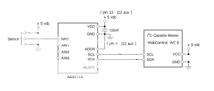
I went out to add another 100nf cap, and while I did that I also shortened every lead I could.  I have read now that i2c likes to have its slaves close at hand, and your mention of noise and jitter induced me to shorten even more, the i2c bus pair between the wc8 and the little protoboard where the adc is.   It's about 6" now.  I also replaced several jumpers with shortest versions.

When I came back in, voila, lovely data.  quickly wrote code to see all four inputs twinkling their values in the first four VARs.   success!

being curious and stubborn, I went back out and pulled the extra cap.  all FFFF.  further fiddling showed that the new cap, or both, gives data; the original cap gives 65535.  It's a tantalum, new, and was polarized properly, so no idea there.  doesn't seem to have been any issue with the wiring, only the cap.

took the opportunity to test other modes, single read and continuous both work fine.  the data rate at the default 128 sps also works.   and those delays don't need to be so long.  with no delay, in singleread, all the reads are the same low value; setting it to 10 is enough for the reads to stabilize at their meaningful steady values.
 
here's some working plc, for singleread and pga +/- 6v on ai0:

    I2CWRITE 1 0 144
    I2CWRITE 0 0 1
    I2CWRITE 0 0 193
    I2CWRITE 0 1 131
    DELAY 10
    I2CWRITE 1 0 144
    I2CWRITE 0 1 0
    I2CWRITE 1 0 145
    I2CREAD 0 0 RAM11
    I2CREAD 0 1 RAM10
    SET VAR1 RAM1L

this gives 4836 +/- 1 for ai0, which is wired to 1.1vdc.  reading the other inputs, ai1 is at 5vdc and reads 65534 rarely dropping momentarily to 63553, ai2 is grounded and reads ~2975 +/- 5, and ai3 is floating and reads ~2775 +/- 5.  the time variation in the values is quite low and tolerable.  there's still some work to do playing with the scaling but I can see that it is basically working.

so this is good, I can get at least four of these sensors into the wc8, that's going to help immensely, thank you. I still need to test with the additional boards, to make sure it can handle more at once.

now I'm on to the 16 bit i/o MCP23017  :)
 
Great report!
Could you please give more details on where did you add capacitors?  Did you add RC circuit on your inputs?  If there is any drawing, that can help others a lot, too! :nutz:
 
the only cap atm is the 0.1uf 50v tantalum between Vdd and Gnd on the ADC board.  the wc8 is powered by a 9v 2A switching voltage adapter, I haven't added any capacitance at that terminal block.  thought about it, but so far nothing seems to be needing it.  maybe once the i2c bus is loaded up with every sensor on ebay?  :)

oh, so you want a picture?
ads1115%20schem_zpsxen3hljy.png

yes, I liberated that from the data sheet
 

saw the pm about filter caps on the analog inputs.  I haven't done that & honestly it doesn't make sense to me.  when I read the forum earlier, I saw the ACS712 current sensor post, needing to rectify and filter the output when it was used on AC lines, but these voltages are essentially constant in the short term, or change very slowly.  the sensor is just a moisture reactive resistor in a divider, or maybe a bridge, fed w/ 5v, and the substrate humidity takes hours to drop enough to seem 'dry'.  well less than a day, but still hours.  I see a little jitter that looks like noise, but atm it's not enough to cause a problem with the way I will be using them

on the wc32 I'd like to plan on using four of these with the acs712s on a box of SSRs feeding 120vac outlets, and have data on realtime current for each circuit.  that should be fun and take some filtering.  I also have some split core sensors that work better but they are $8 each and I don't want to buy 16 of them
 
Is there any way to remotely/programmatically upload new plc code, other than perhaps using autoit to stuff new text into the PLC Program browser window ?
 
There is no other way other than using browser to upload PLC code. It should be put behind firewall not allow anyone to access the HTTP port, since that is critical for not being hacked.
 
Back
Top