Does this meet code: adding a current transformer in a load center

etc6849

Senior Member
So, I'm thinking about adding a split core current switch on a branch circuit in my load center to give power state of a large load:
http://www.amazon.co...keywords=cr9380

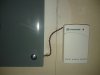
The wires from the current switch would come out of the load center and go into an X10 DS10A wireless door/window switch...

My question: does this meet NEC requirements? I can't think of any that would be violated by adding a CT, but I thought I'd ask to be sure.

If this does not meet code, what is the best approach? I'm also considering making an extension cord with the DS10A and current switch built in, but I think this would violate code since it would involve combining the DS10A and a 20 amp circuit into a single gang box.
 
While the wiring is subject to the NEC, in this case, since the sensing portion is clamped around the HV load, nothing really to cite for a code article or what it would or would not meet, with the exception of the portion of wiring feeding the xmitter, which only has to be secured to the building "fabric" in a neat and workman-like manner.
 
It is the same scheme Brultech uses, they have you run the LV wires out of the panel and to their controls. You can check their site (FAQ/Manuals/Forum) for details...
 
Thanks guys. I've installed the CT, but I didn't add another enclosure. I just let the wires hang out and installed the load center door back on. I'm guessing this is ok since it is "neat in a workman-like manner." I guess I could secure the wire to the wall if you think it's needed...

The CR9380 + X10 DS10A is one cheap wireless solution to my problem! I'm using the DS10A to sense when my 3HP 220V table saw is turned on, then I've installed an Intermatic Z-Wave motor contactor on a large 3HP 220V dust collector. Now when I turn on my table saw, my dust collector automatically comes on! How neat is that!?!
 

Attachments

  • IMG_20120626_225957.jpg
    IMG_20120626_225957.jpg
    19.2 KB · Views: 11
Nope, code violation. Wiring should be run through a bushed or grommeted opening, not between the panel face and back enclosure. Easiest would be to install a chase nipple or romex connector into an existing 1/2" knockout in the panel
 
The wiring can be left exposed if it were Class 2 or 3, but I don't see anywhere on the CT (or in the specifications) that it is Class 2 or 3 power limited. In order to use power limited wiring techniques, (under Article 725), which allows the exposed wiring, the power source must be a Class 2 or 3 LISTED source. A LISTED source must be labeled as such.
 
$.02

The unit itself is power limited, factory carries all the listings. Very common item used in PLC's and automation, although it's typically all contained within a control cabinet.

The wireless transmitter is inherently power limited (DC power, batteries) as well as not covered via the NEC, the wiring for the CT is already power limited in nature, as it is only a signal wire in the ratings listed on the tap. The unit is self powered via induction, so it's not getting power from an outside source.

The tap doesn't truly come into the equation as far as HV wiring goes, as the conductors are separated from it via a permanent non-conductor, it's only used as an inductor.
 
Back
Top