Electronics question

cestor

Active Member
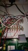
I have an omnipro 2 with lots of sensors attached. As each of these sensors require their own +ve and GND supplies, what I did is run a couple of wires from the omnipro 12v and ground output to a terminal block which then supplies all the attached sensors. See the picture; the top of each block shows the sensors coming in while the bottom of the block bridges the supply. 
 
However, I am seeing some funny behaviour which is that I could be working on one sensor and it could trigger a sensor in an entirely different zone. 
 
For example, yesterday, I ran power to an Arduino from the above terminal block, and when I also plugged in a USB plug into the Arduino, it blew the Arduino, and at the same time, triggered several Omnipro zones, stopped a console working and triggered both the internal and external sirens.
 
I have an idea that the problem may be due to floating grounds which are different between the sensors, and I have many +12v and GND connections going to the same place in the terminal block. The case itself is totally earthed. 
 
So here are my questions:
1. does this seem like a likely cause? 
2. Is it bad practice to use the same supply connection for multiple +12v  and GND
3. Is there a solution that doesn't involve a terminal block that is 50 wide and takes up a huge amount of space...


Attachments

  • IMG_20170503_160332507.jpg
    IMG_20170503_160332507.jpg
    109.4 KB · Views: 30
A difference in ground potential is certainly one possibility, but it would be helpful to know more about your setup.
 
When you ran power to the Arduino from the terminal block, did you have some 5V regulator in between them?  I assume yes.
 
How were the grounds between them referenced?
 
Was the USB plug connected to a power supply or your computer?  Desktop or laptop?  Laptop running on its power supply or battery?
 
Did your Omni Pro recover, or was there damage to the unit?
 
No, it was a straight 12v. I had the arduino running fine off a different 12v supply with the USB also connected.
 
There is no reference between the ground on the terminal block and the ground of the USB (hence my comment re floating grounds...) 
 
USB was connected to a minimac, in turn connected to an apple power brick, connected to the manis

powered off the Omnipro, unplugged the battery and all was fine again
 
Here installed a micro router (custom OpenWRT OS) inside of the OmniPro 2 panel.  I do not have the WLAN radio enabled.
 
Power comes from a small automotive 12VDC to 5VDC micro USB device.  It has been configured like this now for over a year with no issues.
 
Here is a picture.
 
HAI-MicroFirewall.jpg
 
Looking to switch over to a small bucky type of transformer to shrink down the footprint (also rewiring a bunch of stuff) or just taking the circuit board out of the current automotive style transformer and putting it in a tiny plastic case.
 
Purchased a couple of these and installed one a couple of weeks ago.  It is a tiny 12VDC terminal block with an LED.
 
12VDCwithLEDterminalblock.jpg
 
I am doing similiar in the Leviton 41"  panel using a 12VDC power supply which feeds a couple of 12VDC devices and 5VDC devices.
 
Personally I would add up the number of 12VDC devices connection to check on the total power draw before adding more stuff.  I mean you did mention you have a lot of 12VDC devices already connected.  That is me.
 
I agree with Pete.  Adding up the total current draw is always a good idea, since the panel can only provide 1A total, IIRC.
 
Since this happened when connecting the USB cable from the minimac to the Arduino (and not when connecting the Arduino to the Omin), I'm suspicious of a ground potential difference between that minimac and the rest of your setup.  You can try using a volt meter to see if there is any difference between the Omni's ground and the ground on the mac without plugging in the USB cable.  I don't know if the logic ground on the Omini is earthed or floating.  I do know that, typically, the output of a laptop-type power supply is floating.  The one on the mac might be earthed, however.
 
Do you know what component(s) got damaged on the Arduino?
 
Edited to add: is the earth ground on the Omni's terminal block connected to anything, and if so, what?
 
The earth ground on the Omni goes to the main house earthing bar.
I haven't tested the arduino (it doesn't power on now at all) but reading forums, it seems likely to be the voltage regulator. 
 
But the current draw idea makes a lot of sense - if there's too much being drawn, then it will have the effect of making other zones drop out. Maybe I will measure and if so, replace the feed to the block with a DC power supply.
 
Excessive current draw on the Omni isn't likely to damage the Arduino, though.  It would just drag down the +12V aux power rail in the Omni and cause the Arduino to shut down.  It would certainly make the Omni angry, though.
 
I think that you might still have something else going on there.
 
Also, what else was connected to the Arduino?  Which model Arduino?  If that had a linear regulator and you had an excessive load on the Arduino, then the linear regulator might exceed its power rating.  Dropping 7V across that device (assuming 5V output) doesn't leave much current capacity.
 
cestor said:
It was a Mega 2560 clone, DC input is rated for 12v
 
What was connected to the Arduino?
 
The regulator on the Arduino is a TI LP2985.  Just doing some rough numbers at 12V in, we're dropping 8.7V across the regulator.  The thermal impedance is listed at 169 deg C per watt, and the max junction temp is 125 degrees C.  Let's assume that ambient was 25 C, so that give us an allowable temp rise of 100 deg C.  That allows us 0.59 Watts of dissipation in the device.  We can take that and divide by the voltage drop and get our real max current of about 68 mA.  So, keeping the Arduino and everything it powers or drives at under 68 mA is important to keep the regulator under its temperature limit at room temperature.  As the ambient temperature rises, the current capacity drops.
 
I just grabbed the worst thermal resistance from the datasheet.  It's likely better than that, but you get the idea.
 
Edited to add: That isn't to say that this is the root cause, either.  I would still check for some ground offset.
 
Here your post made me change the power supply for the micro-router (even though it has worked fine without wireless enabled).
 
Shift the power supply to a POE (with backup) connection to adjacent 42" Leviton panel (with a managed switch and POE switch).
 
Removed 12VDC to 5VDC automotive transformer and went to the using TP-Link POE power splitter set to 5VDC.
 
so I tried to read the amperage this morning off the power block and as soon as I touched the probes to the connections, it tripped some of the attached zones on the OP2.
 
You cannot read amperage from the 12VDC power outputs. 
 
I had an issue with the car drawing too much power from the battery after shutting it off (lingering BT module would stay on while telephone remained on in the house with the car in the garage).  Only thing I could measure was draw in mA's connecting the multimeter in series.  It ate three new batteries until the BT module was reprogrammed even though the MFG denied that their was an issue with their stuff.
 
It's much easier to just add up your connected devices utilizing 12VDC.  
 
Biggest power draw here used to be exterior horn until I disconnected it.
 
Original testing with micro router was an exterior 5VDC power supply (2 AMP) until I knew it worked. 
 
A bit over kill here on power and lightning stuff and grounding went to a separate subpanel for consoles and another one for 12VDC exterior to house sensors power supply.
 
Why can't you read the amperage from the 12v power output?
Also, how would I know what the draw is on each device if I can't measure it?- is it a case at looking at the datasheet on each one?
 
pete_c said:
Here your post made me change the power supply for the micro-router (even though it has worked fine without wireless enabled).
 
Shift the power supply to a POE (with backup) connection to adjacent 42" Leviton panel (with a managed switch and POE switch).
 
Removed 12VDC to 5VDC automotive transformer and went to the using TP-Link POE power splitter set to 5VDC.
 
Pete, some of those automotive adapters use switching regulators instead of linear regulators.  The switching ones are generally very efficient.
 
You can crack it open and have a look to see which kind it uses.
 
cestor said:
so I tried to read the amperage this morning off the power block and as soon as I touched the probes to the connections, it tripped some of the attached zones on the OP2.
 
In order to read current, you need to put your meter in series with the circuit.  On the "current" setting of your meter, it's going to look like a short, and if you touch the probes across the connections (instead of in series with them) then it will crash the 12V aux power rail.  You might want to check the fuse in the meter after that, as it might have blown.
 
You can just add up the spec'd current on all devices connected.  The spec'd current should be conservative.
 
Back
Top