ELK M1RB and M1XOVR

gasbie

Active Member
Hello, I'm designing my elk m1 gold installation in vision but I just gat stuck somewhere. I'm a newbie to this, so all help will be appreciated. 
1). What is the difference between M1RB and M1XOVR? I do understand that M1XOVR has voltage and relay while the other is only relay. When I looked at the diagram in the manual, they were  both used for similar application. I guess my question is when would I need the voltage output of the M1XOVR? can anyone give an example of what M1XOVR can do that M1RB can't do. 
 
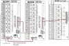
2). is it possible to power the m1rb or M1XOVR with my altronix power supply. if so, how? I see you need the J16 to make the connection between relay board and M1 Gold control, but 12v power outut is already part of the cable. will i cut out the 12+  and neg cable off the j16 cable.  I have attached a diagram to show what i'm talking about. 
 
Thanks


Attachments

  • m1rb.jpg
    m1rb.jpg
    58.9 KB · Views: 18
Outputs 7-16 of the M1 board, and 8 of the outputs on an M1XOVR are voltage outputs.  This means that when the output is on, there is 12V present, and the output can provide up to 50 milliamps of current. 50 mA isn't much in terms of what it can power.  You could use it to light up an LED, or control a small 12V relay, or other small devices.
 
If you want to control things that require more than 50 mA, then relays are the way to do that.  You could put a single relay on one output, but if you have a need for multiple outputs to control multiple relays, the the M1RB is the thing to use.
 
The M1XOVR also has 8 relays built in, on the other 8 outputs.  If you want 16 relay outputs, then a M1RB combined with a M1XOVR will give you that.
 
As to providing power to the boards, yes, you could use an Altronix power supply for that.  I would probably try and avoid powering the M1RB this way, to avoid having to cut wires in the wiring harness. 
 
But if you really need to, you would do as you described. For the J16 connector, cut the red and black +12V and -12V/NEG wires between the two boards.  But cut them at the M1 end, not at the M1RB.  Then use the cut wires to connect to the Altronix.
 
Connect the red wire from the M1RB to +12V/DC+ terminal on the Altronix, and the black -12V wire from the M1RB to the Altronix  -12V/DC- (Common) terminal.
 
You will also need to tie the M1's NEG terminal to the Altronix DC- terminal, so that everything has a common signal ground.
 
To power a M1XOVR from an Altronix power supply, connect the NEG terminal on the M1XOVR to the Altronix -12V/DC-, and also the the Elk NEG terminal.  Connect the +12V terminal on the M1XOVR to the Altronix +12V.
 
This leaves you with a 3-wire data bus connection to the M1:  Data A, Data B and NEG.  But not +12V.
 
Make sure that you DO NOT connect +12V from the Altronix to the M1's +12V !!
 
RAL, you are the best. thanks for your taking time out of your busy schedule to respond to my question. I think I will just power it off the M1 control board. That saves me a headache. I have more question about the m1xovr. So output 1 thru 8 on the m1xovr is a relay that functions just like the M1RB, am i correct? and output 9 thru 16 on the m1xovr provides the voltage output, am I correct? so let's say i want to power a led strip light with M1XOVR, I wouldn't need an external power supply as long as it does not exceed 50mA, but if I want to power the same LED with M1RB, then i will need an external power supply, am i still right? thanks
 
Yes, outputs 1-8 are the relay outputs and 9-16 are voltage outputs.
 
Think of the relay outputs as on-off switches.  They don't supply any voltage or current.  They just connect the two wires at the terminals together.
 
You could use the voltage output to drive a couple of LEDs, but a LED strip might require more than the 50 mA a voltage output can provide.  So if that's the case, then yes, you would need an external power supply for the LED strip that you could control with a relay output.
 
When you want to control something that has an external power supply, then the relay outputs are the right ones to use.
 
When you want to control something that needs a voltage as an input, then the voltage outputs are what you probably should use, as long as you can stay within the current limit.  An Elk 120 voice module would be an example of something that would be used this way.  It has 4 inputs that make voice announcements when a positive voltage is applied to the trigger terminals.
 
Thanks RAL. Now, i understand. Now that you mentioned ELK 120, I have sever questions about that. I want to wire my door bell in such a way that when some one presses the door bell, it will announce it will triger the ELK 120 and announce that "someone is at the door", or if someone opens the front door, it triggers the elk 120 to announce through the speaker that "someone just opened the front door". what will my wiring be like on this. Thanks
 
Thanks RAL. Now, i understand. Now that you mentioned ELK 120, I have sever questions about that. I want to wire my door bell in such a way that when some one presses the door bell, it will announce it will triger the ELK 120 and announce that "someone is at the door", or if someone opens the front door, it triggers the elk 120 to announce through the speaker that "someone just opened the front door". what will my wiring be like on this. Thanks
 
You don't necessarily need the Elk 120 to make voice announcements.  The 120 will let you record your own announcements, for a total of 4 different announcements that can total up to 8 minutes (e.g. four different 2 minute announcements).
 
But without the 120, you can write rules on the M1 that will make it speak in its own synthesized voice. The M1 has a vocabulary of over 500 words.
 
To accomplish what you want to do with the doorbell, use an Elk 930 doorbell detector to sense when someone rings the bell. Connect the 930 to a zone input on the M1. Connect a door contact for the front door to a different zone input.
 
Then, write rules that trigger on the 930 zone input or the door contact input to speak a System Miscellaneous message. You can have up to 10 misc messages of 6 words each.  So one message can be "someone is at the door" and a second message can be "someone opened the front door,"  each triggered by the corresponding input.
 
RAL, thanks for all your help. Can you explained what a positive or negative trigger is in relative to ELK operations. For example, I know that you can use the voltage output on ELKM1OXVR as an input for ch1 thru ch8 on ELK124. correct me if am wrong, let says I want my custom message to announce when someone open the door, I will have to write an ELK rules that will say something like "if front door opens, trigger output 7"; then elk knows to make the announcement on ch1 since output 7 of the ELKM1OXVR is attached to it? So, I will say elk triggers are RULE CONTROLLED, right. 
 
my second question, I have attached a picture of elk924. in the picture elk924 simultaneously switch between 12 V DC and 120 V AC. Correct me if am wrong, the +12v and the GND coming from the control panel is used to energize the relay and the "+ alarm output" is used to trigger the relay to respond to condition as defined by ELK rules? 
 
Is there any major difference between +ve switched trigger and -ve switched trigger?
 

Attachments

  • ELK924.png
    ELK924.png
    314.8 KB · Views: 17
gasbie said:
Can you explained what a positive or negative trigger is in relative to ELK operations.
 
The terms positive and negative trigger describe which direction the voltage is changing in at the trigger input. 
 
For a positive trigger, the voltage would normally be around zero volts (common/ground), and when it changes to something near +12V, that causes an action, such as the Elk 124 speaking.
 
For a negative trigger, the voltage would normally be around +12 volts, and when it drops to around zero volts, that causes the action.
 
 
gasbie said:
I will have to write an ELK rules that will say something like "if front door opens, trigger output 7"; then elk knows to make the announcement on ch1 since output 7 of the ELKM1OXVR is attached to it? So, I will say elk triggers are RULE CONTROLLED, right. 
 
What you are saying is basically correct, though I would probably have phrased it a little differently.  I prefer to say the Elk outputs are controlled by rules since a rule can control the duration of an output change rather than just initiating or triggering the change.
 
The Elk rule would look something like this:
 
WHENEVER Front Door (Zn 1) BECOMES NOT SECURE
          THEN TURN Output 7 (Out 7) ON FOR 1 SECS
 
This assumes you have the 124 jumpered for 1-shot operation with J2.
 
 
gasbie said:
 my second question, I have attached a picture of elk924. in the picture elk924 simultaneously switch between 12 V DC and 120 V AC. Correct me if am wrong, the +12v and the GND coming from the control panel is used to energize the relay and the "+ alarm output" is used to trigger the relay to respond to condition as defined by ELK rules? 
 
Is there any major difference between +ve switched trigger and -ve switched trigger?
 
 
Yes, the 924 relay receives its power from the +12V and GND terminals of panel (+VAUX and NEG on the M1).  The "+ alarm output" would be a voltage output from the M1 or a M1XOVR.
 
If you have an Altronix power supply, you could use that to power the 924 instead. You would still use a voltage output to trigger the 924.  But in order for that to work, you need to make sure the NEG terminal of the M1 is connected to the Neg terminal of the Altronix.
 
I'm not sure where you are finding the terms +ve and -ve, but I would say that they should be the same as positive and negative triggers.
I'm guessing that you are finding this on some other board or device, and depending on what it is, it might not be a 12V device and +/-ve might not refer to 12V levels. 
 
Thanks RAL, I'm learning alot from you response. so basically, it's a matter of choice if  I want to trigger the elk924 with either positive or negative switch?
 
Also, I have realized that you emphasized so much on "connecting the neg of the M1 to altronix neg", I know its called common grounding, can you explain this. Do i do this on every device that is not powered directly by M1? what is the general rule?
 
referring back to the attached picture, I want to do something just as shown in the picture, but I know certainly that I don't want to put the high voltage part of the relay inside the structured panel, so is this where I will use the xovr relay in the panel to trigger ELK924 (outside the panel) to control the high voltage device?
 
Another dilemma i having is, I'm using the voltage part of my XOVR to trigger ELK 124, now, how would i connect 2 XOVR and a relay board together. I have attached another pix. let me know if this is correct. Thanks in advance.   
 

Attachments

  • multiple xovr.jpg
    multiple xovr.jpg
    120.2 KB · Views: 17
You don't necessarily connect the XOVR's together, they are bus devices and need to be wired as such, however you need to pay attention to the maximum current draw of ALL connected relays to the M1. XOVR's are power hungry.
 
The M1 provides switched positive outputs or you would do the same via the relay boards. Switched negative is not a common US panel application; Generally only seen in world marketed panels.
 
Generally bonding the common negative is a best practice, not completely necessary, but it eliminates a lot of potential problems. It is necessary in applications when you're powering anything running on the data bus otherwise the differential and reference ground isn't the same.

In the specific case of the 124, you could use the LV triggers directly into it as long as you paid attention to the total load presented to the M1.
 
As DEL said, you can just daisy chain the M1XOVRs together using the data bus screw terminals.  If you really wanted to, you could use a ELKW018B ribbon cable between the J1 or J2 connectors.  That cable is 18" long, and if you are mounting the XOVRs close together in the same enclosure, you may end up with a lot more cable length than you really need, and you'll have to tuck it away somewhere.  To me, it's a lot easier just to use a short length of 22/4 cable on the screw terminals.
 
The ELKW018B used to be not listed as a permanent installation item or interconnect. Not sure if they changed that or not, but it's not listed for use at the M1 itself, only for testing purposes.
 
does anyone knows the guage number for the 12 conductor "Flying Lead" Wiring Harness that comes with the XOVR. is it 18awg or 22awg? I'm trying to make one up. Thanks
 
I would say it is 22 gauge.  Definitely not 18.  For the small amount of current it needs to carry, 22 gauge is more than adequate.
 
Back
Top