If it were me, I would use 18-4 for the WSV rather than Cat5/6 cable. It's just the better choice for the load you need to handle. I try and stay away from using multiple conductors of a smaller size whenever I can. It doesn't matter whether you go with stranded or solid wire. That comes down to personal preference.
You are using an out of date browser. It may not display this or other websites correctly.
You should upgrade or use an alternative browser.
You should upgrade or use an alternative browser.
KHouse Elk M1 Install (Questions and Help For A Rookie)
- Thread starter KHouse
- Start date
Question regarding conflicts.
I've got most everything wired up, enrolled the XEP and the wireless Honeywell module via the keypad, and found the XEP in the setup on the RP.
When I clicked to use the setting for the XEP, I got a conflict error screen with everything highlighted yellow. Had the option to delete, or send to device, etc. I chose to send to device to make the M1 and RP on the same page with what's going on.
Was that the right thing to do? Why did all 16 zones show up as a conflict? Is that normal for a new installation?
My buddy can't make it out today, so I'm all alone figuring out this phone wiring again. :blink:
So here goes.
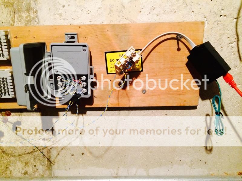
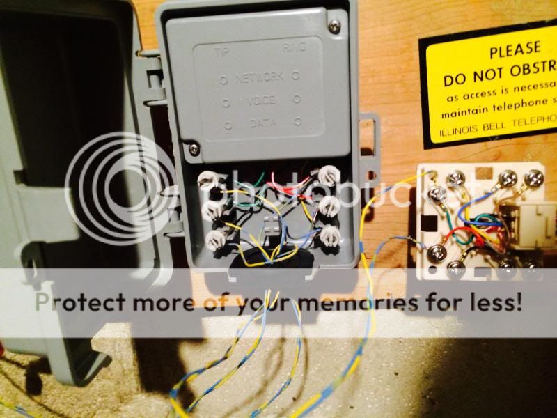
After the advice here, and generally Googling whats what...I've connected the middle pair from the grey box (voice lines), to the RJ31x. The 2 lines from the grey box had corresponding green/red lines coming in to them, so connected them to the corresponding green/red lines on the RJ31x. Then I connected the RJ31x to the Elk 952 surge suppressor (I know it still needs to ground, and the whole setup will be cleaned up/mounted nicely)...then the 952 into the red Cat5e cable, which runs up to the M1.
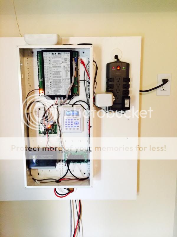
I believe this was correct, and essentially I'm just taking the 2 voice lines (red/green) and dedicating the phone line soley to the M1, and avoiding all other lines in the house. Now, the red Cat5e runs to the M1, and at this point I need to cut the connector tip off, and connect the white/blue pair into the tip/ring as mentioned earlier in this thread. Would that be correct.
Assuming I've done this correctly, my last item is to get clarificaiton of which color of the Cat cable needs to be connected to the tip/ring connections on the M1...and...is it just these 2 that I need to connect, or something for the R1/T1 as well with this setup? The manual shows Telco line into the red/gree on the RJ31x, and then the R1/T1 out to the house...but I'm not running anything out to the house.
Thanks again for the help folks! :rockon:
KHouse said:I believe this was correct, and essentially I'm just taking the 2 voice lines (red/green) and dedicating the phone line soley to the M1, and avoiding all other lines in the house. Now, the red Cat5e runs to the M1, and at this point I need to cut the connector tip off, and connect the white/blue pair into the tip/ring as mentioned earlier in this thread. Would that be correct.
I think you've got it right.
KHouse said:Assuming I've done this correctly, my last item is to get clarificaiton of which color of the Cat cable needs to be connected to the tip/ring connections on the M1...and...is it just these 2 that I need to connect, or something for the R1/T1 as well with this setup? The manual shows Telco line into the red/gree on the RJ31x, and then the R1/T1 out to the house...but I'm not running anything out to the house.
The incoming line should be on the Blue/White pair of your red Cat5e cable, with the Blue wire being Ring and the White-with-Blue-stripe wire being Tip.
If you don't want to connect the RJ31X T1/R1 terminals back out to the rest of the house jacks, then you don't need to connect anything else.
System is up, able to arm/disarm/be activated by a door opening, etc. I've got just 3 of the many sensors installed, so will be spending much of tomorrow doing the remainder.
Another question on the phone though: The alarm panel works fine sometimes, shows no errors,etc...but sometimes, I get the message "failure to commu" on the keypad. Additionally, sometimes I get that error + "Phone Error". And then again, sometimes no errors at all. I've had each of those happen several times off and on today.
Any idea what it is failing to communicate with? Some senors? (although it doesnt list any sensors on the keypad that are bad and it states ready to arm). The central station? Something else?
I do not have a central station hookup yet. The plan is to use alarm relay, but a while back we switched our home cable plan to just internet/tv and dropped the land line service...so need to call them and get service back before I call Alarm Relay.
Regarding enrolling the glassbreak sensors:
What are the proper settings?
Definition I've chosen 04 = Burglar Perimeter Instant (based on searching another thread on this forum)
I've left it Type 0 = EOL Hardwire/Wireless (Should this be normally closed, normally open, etc?) Can someone explain what sensors would use the normall closed/open?
Under the supervision drop down, I've chosen #3 (Fire Supervision), the instructions state to choose #3 RF supervision, but I don't see any such choice.
Loop 1
For doors with Recessed 5818MNL transmitters I've used:
Burglar Entry/Exit 1
Type 0 = EOL Hardwire/Wireless
Supervision = 1 Normal Supervision
Loop 1
Just for sake of confirmation, can anyone confirm these are the correct setting for door/window sensors?
I'll take a shot at helping out here, but I can't claim to be an expert, especially on the M1XRF2H setup.
I think the errors you are getting on the phone line are due to the fact that it is not a live line. The M1 checks the line periodically to make sure the connection is good, and will give errors if doesn't see proper voltage levels.
On the Zone Type, Type 0 (EOL Supervised) implies that there is always a connection with some resistance (2.2k). Type 1 (Normally Closed) implies that there is no EOLR and a short (near zero ohms) should normally be present. Type 2 (Normally Open) also implies no EOL, and that an open circuit should normally be present.
When you choose Type 0, it doesn't matter whether it is a normally open or normally closed contact since the panel can detect the end-of-line resistor and if the zone changes to either to an open or a short, it will trigger the alarm.
Many contacts come in both NO and NC types, and some offer both NO and NC terminals, allowing you to use it either way (this is called a Form C). If you don't have end-of-line resistors installed, then usually an NC contact is preferred.
In the case of the wireless contacts, the wireless transmitter and receiver provide RF supervision, so you can treat this as a Type 0.
For the glassbreaks, from what I read in the M1XRF2H manual, it makes me think that you want to select transmitter supervision type 1 (normal supervision). I don't see any reference to an RF type in this manual or in the M1 manual. Are you looking at some other set of instructions?
I think you've got the settings right for the 5818MNL.
Thank you RAL.
To follow-up regarding the phone line. Through trial and error I was able to determine I can arm/disarm, or arm and set off the alarm (open a door for example), and all that with no problem. The phone line error went away when I plugged in the phone line to the M1. The only time I get the communication error, is if I press one of the F keys to set off the fire/police/medical alarms. Then right after that alarm, I get the communication error. And most likely it's because I don't have the land line service back up yet.
Thanks for the explanation on the zone types.
Regarding the glassbreaks, the RF type is mentioned on the paper instructions that come in the box with the glassbreak sensor.
So far all doors and windows are setup and working without issue.


