Desert_AIP
Senior Member
After conducting a water pressure/GPM test I discovered I needed 12 zones for my irrigation system instead of the 8 I originally allotted during my install.
I'm using 23 of the 24 voltage outputs I have on my Omni Pro system already.
8 reserved for the irrigation zones and the other 15 for miscellaneous tasks like garage door & gate controls, thermostats, water valve, audio mute, etc.
So my option to add more outputs would be to add an additional Expansion Enclosure.
An expensive option, especially since I only need 3 more outputs and I don't need any more inputs.
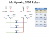
After playing with the wiring diagram, I came up with a way to turn 8 Omni voltage outputs controlling an 8 SPDT relay board into 12 separate endstate results.
Essentially each pair of outputs and relays produces 4 different results, like two digit binary.
Since all off is one of the desired results, that gives me three control zones for every two voltage outputs controlling two relays.
Output 1 is wired to control the coil on relay 1, output 2 is wired to control relay 2.
The two legs of the 24VAC valve control transformer are split and wired to the common terminals of relay 1 and 2 respectively.
The valve solenoids are wired in such a manner that the combination of ON signals will turn zone 1, zone2, or zone 3 on.
No more than one valve can be turned on at a time.
When neither output is ON, both relays are in the NC position which breaks contact to all valves on one leg or the other of the 24VAC and all valves are off.
When output 1 is ON, relay one shifts to the NO position, and completes the circuit for zone 1 (but not zone 3).
When output 2 is ON, relay two shifts to the NO position, and completes the circuit for zone 2 (but not zone 3).
When both outputs are ON, both relays shifts to the NO position, breaking the circuits for both zones 1 and 2 and completing the circuit for zone 3.
I attached a picture to clarify.
I'm using 23 of the 24 voltage outputs I have on my Omni Pro system already.
8 reserved for the irrigation zones and the other 15 for miscellaneous tasks like garage door & gate controls, thermostats, water valve, audio mute, etc.
So my option to add more outputs would be to add an additional Expansion Enclosure.
An expensive option, especially since I only need 3 more outputs and I don't need any more inputs.
After playing with the wiring diagram, I came up with a way to turn 8 Omni voltage outputs controlling an 8 SPDT relay board into 12 separate endstate results.
Essentially each pair of outputs and relays produces 4 different results, like two digit binary.
Since all off is one of the desired results, that gives me three control zones for every two voltage outputs controlling two relays.
Output 1 is wired to control the coil on relay 1, output 2 is wired to control relay 2.
The two legs of the 24VAC valve control transformer are split and wired to the common terminals of relay 1 and 2 respectively.
The valve solenoids are wired in such a manner that the combination of ON signals will turn zone 1, zone2, or zone 3 on.
No more than one valve can be turned on at a time.
When neither output is ON, both relays are in the NC position which breaks contact to all valves on one leg or the other of the 24VAC and all valves are off.
When output 1 is ON, relay one shifts to the NO position, and completes the circuit for zone 1 (but not zone 3).
When output 2 is ON, relay two shifts to the NO position, and completes the circuit for zone 2 (but not zone 3).
When both outputs are ON, both relays shifts to the NO position, breaking the circuits for both zones 1 and 2 and completing the circuit for zone 3.
I attached a picture to clarify.