Need help installing GE 3-way Z-Wave switch!

I must say for the record, GE or any other manufacturer is not to blame, the blame should go to the electrician that didnt wire for a 3 way switch by using travelers from master to slave box.

While I agree that travelers from master to slave would solve this problem, I understood that the way it was wired would still be code compliant (at least until recently) using the old, standard switchology. This appeared to be a variation on the switch loop idea, in my mind. While one may argue that it might be good practice to do as you suggest, I find it hard to blame an electrician when it would have been code compliant.

I understand the new code requires a neutral in every box. This requirement would have the unintended effect of tending to reduce the instances of the type of wiring approach found here, in my mind.

I would call GE and ask them if feeding that slave switch from another location requires a hot on the same phase or different phase (I think it should not matter since its not feeding your fixture, the master switch supplies both hot and neutral)

I believe he did this, but I misunderstood other things, so it may be best, again, to further confirm.
 
the code does not say which wiring method is compliant or not per se, is not a manual with sample wiring diagrams. 
there is more than one way to wire 3 and 4 way switches or variations so to speak.

the reason why I blame the electrician is because I don't see a reason to deviate from running travelers between switches, simply not a common practice. it's not like he was gonna save on wiring or installation time.
Bringing wires from 2 points then to a light fixture was not a good idea, box fill can be an issue and it will not be practical to have access to all that make up or splices specially if the box is at a high celling. A light fixture should only have a supply wire (hot neutral and ground) and maybe another wire feeding another fixture downstream.

Technically you don't need a neutral wire at all times in every box when it comes to switches. But you do need it whenever there is a load attached that you need to control, hence the need lately to have a neutral in most dimmer switches or occupancy sensors or devices that need to control the flow of electricity by sampling both supply and return like GFCI's 

commercial dimmer panels require the use of a dedicated neutral wire per circuit, when in residential 2 hot wires connected to 2 differing phases in your panel can share one neutral.
example a receptacle that feeds under a sink a disposal and a dishwasher, one receptacle plug goes to a hot on A phase the other to B phase but only one neutral back to the electrical panel.

I would not blame any manufacturer as stated before. it would be very difficult to make products that could work on any house regardless of the existing wiring.    
 
Thank you guys very much for your input on this topic. As stated before I cannot run any additional wire, but I will sure try run hot from another circuit to the slave where applicable. I think there was a lot of great information posted in here that will be helpful to others. I think GE Jasco should have some accountability as they have admitted the switch can only be used in 1 of 7 standard schemes. ACT should have taught them better! Anyway, now that this is pretty much resolved, I am working on another issue. http://board.homeseer.com/showthread.php?t=146683
 
myyaz33, brother, as I stated before dont blame Jasco for your particular application.

Yes there are many variations to wire 3 or 4 way switches but by no means "standard" in any way.

The electrician could wire in any way he feels as long as it passes inspection and it is code compliant, leaving the burden to the home owner or the next electrician when it comes to work with your electrical and modify or add something.

In my honest opinion after working on the diagram, the Jasco design will work with most people out there, it will certainly work in my house and almost every where I installed a 3 or 4 way circuit. I still can't understand why your electrician wired things the way he did, when fixture boxes are known to have very limited space for all that splicing that will take place in in scenario.

Keep an open mind on this, thats my suggestion. It was my pleasure to help, and I praise your patience, for not being an electrician you know what you are doing
 
Thank you guys very much for your input on this topic. As stated before I cannot run any additional wire, but I will sure try run hot from another circuit to the slave where applicable. I think there was a lot of great information posted in here that will be helpful to others. I think GE Jasco should have some accountability as they have admitted the switch can only be used in 1 of 7 standard schemes. ACT should have taught them better! Anyway, now that this is pretty much resolved, I am working on another issue. http://board.homesee...ad.php?t=146683

who are you on that forum you linked?
 
I understand UPB and insteon to have similar requirements....each switch has three wires (plus ground): hot, neutral, and load. Most "normal" Z-wave switches were this way as well, I understood. However, this particular Z-wave master switch has four wires (plus ground): hot, neutral, load, and traveler. Because of this, I am not sure that it is accurate to say that these switches have the "exact same requirements" as UPB.
I'm not familiar with other manufacturers, but any Simply Automated switch can be used in a 3-way configuration if desired; and when doing that, you must connect a 4th wire to a traveller to the auxillary location. Therefore you have Ground, Incoming Hot, Outgoing hot to the load, Neutral, and Traveller much the same. That said, I didn't catch previously that the GE switch requires Hot and Traveller; the SAI Auxillary switches require Neutral and Traveller; that could definitely make things harder - I know I only have hot in the remote box in a couple of places.

BTW, I thought the mockup was an outstanding way to describe your installation, perhaps the best I have seen on forums such as this. Is is absolutely complete, compared to the actual installation? Are the existing switch boxes single gang, with no other switches in those locations and no other wires going to the boxes?
Everyone has their ways - for me I like to see more of the real thing - like not just knowing there's 5 wires - but which wires are from which piece of Romex, and what's shared with other fixtures? Of course you never know what happens to that wire past the part you can see, but the more specifics, the easier it is to get a feel what was "probably" done, then test your theories. That, and to be honest I didn't really understand the diagram at first - that seems like a pretty uncommon way to do things so I just assumed I was missing something!

The good news is you can control this light, just proubably with a different style of switch or wiring configuration. For example, you could abandon the 3-way configuration, and turn the Red into a full-time hot which will feed all the way to the auxillary box, then use another Master switch in there in a Virtual Link mode (nothing connected to the load side of the switch - it's just transmitting to the other true Master switch telling it to turn on/off) -- That seems by far like the simplest solution; otherwise explore other brands/manufacturers, or last but not least... I know you've said new wire can't be run, and I don't want to :horse: but if by chance this space has attic directly above it, you don't necessarily have to run wire all the way to the switch locations - just to the fixture... If you can get either hot or neutral (preferably from the same circuit) to the fixture from something else nearby in the attic, you can repurpose existing wires to get the required wires... this could be something as simple as another light fixture near by, or a any piece of romex running in the vicinity.

I did just read the manual for your switch to confirm it'll work fine as a standalone switch (without the slave) - just cap the yellow wire; so you'd just have to purchase one more master switch for the Aux. switch location if you want to go the virtual-3way route... that's the simplest by far since it's all done within the switch boxes with your current wiring.
 
well said Work2play that's what I pretty much suggested previously
since I don't do lighting control yet I like your idea of the 2 master switches I didn't know this was possible
good to know for future reference
 
I was able to make it work by using a hot from another switch in the box for the slave. Works fine and was able to install 5 more switches using this method. A couple places it wouldn't work, so I might try your suggestion with 2 master switches.
 
well said Work2play that's what I pretty much suggested previously
since I don't do lighting control yet I like your idea of the 2 master switches I didn't know this was possible
good to know for future reference

Yes, and and least one manufacturer (Leviton) sells a zwave switch which is a master with no load capability. Leviton calls it a 1 button scene controller and they sell it a few dollars less then the master with load control.
 
Hi everyone,

I was wondering if anyone is having a problem with the light output when connected to these 3-way switches.

My Cree LED cans exhibit flickering and doesn't seem to be as bright. I have had no problems with the regular dimmers that were previously installed.

Also, the 2-way version of these GE/Jasco switches works fine on the same type of light downstairs.

Thanks in advance.

I believe this has been discussed in the MiCasaVerde forum. There was talk about the distance in length that the traveler could be. I have not experienced this problem however.
 
I believe this has been discussed in the MiCasaVerde forum. There was talk about the distance in length that the traveler could be. I have not experienced this problem however.

Thanks for your reply myyaz33.

Will check that out.
 
Hi guys, I hope you don't mind if I jump in here, as I've recently purchased a few sets of these 3-way dimmer sets. I too am a novice when it comes to wiring, but have installed/replaced many standard 2-way and 3-way switches in the past without much problem and I understand the basics of home wiring, including a little about 3-way/4-way wiring. But mostly, I'm just good at following direction when it comes to this stuff.

When I built my house, I had asked for all my boxes to have a neutral AND for my lights to be the last in the chain of switches, so that it would go Power --> Switch --> Switch --> Load/Light.

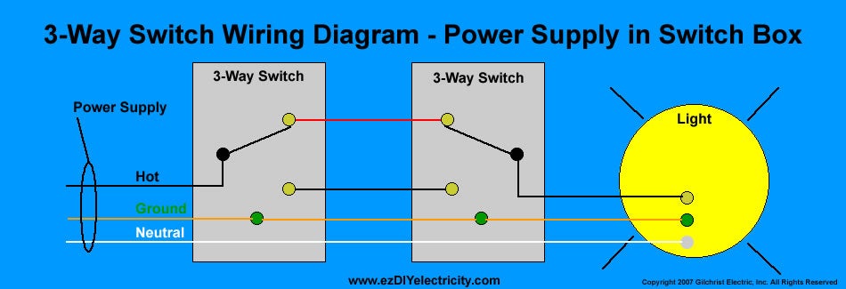
So, I'm trying to figure out how to wire these correctly... currently my three way wiring uses this approach:
http://www.diychatroom.com/attachments/f18/16702d1263774538-3-way-switch-installation-ti070-3w-aube-3-way-switch-wiring-diagram.jpg
16702d1263774538-3-way-switch-installation-ti070-3w-aube-3-way-switch-wiring-diagram.jpg


... to the best of my knowledge.

Switch 1's box - has Black (line/hot), Ground, and Neutral (white) and Black and Red travelers
Switch 2's box - has the travelers coming in, then Black (Load), ground, and neutral (white)

So, If you read that from Left to Right, would the appropriate way to hook up the GE switches be:

PS to Switch 1

Switch 1 - Aux switch
Black (Line/Hot) - to White/Red Aux Switch Wire
Red Traveler - to Yellow Aux Switch Wire
Black Traveler - NOT USED ?
Ground - to Green Aux Switch Wire
Neutral - NOT USED

Switch 2 - Primary Switch
Black (Load) - to Black Primary Switch Wire?
Black (Load) - to Blue Primary Switch Wire?
Black Traveler - NOT USED ?
Red Traveler - to Yellow Primary Switch Wire
Ground - to Green Primary Switch Wire
Neutral - to White Primary Switch Wire

to

Light (Load)

Am I even close to being correct? Let me know if I can provide any more details (or if I should spin this question off in its own thread.

BTW - here's the PDF to the installation manual for those of you who would like to take a better look - http://www.jascoproducts.com/support/manual-downloads/applications/DocumentLibraryManager/upload/45613-Manual-Eng.pdf

Thanks!

:::EDIT:::

Actually, I'm wondering if this would be more correct... basically hook the black traveler cable into the black hot in box 1, so at box 2 the black traveler cable is the hot needed to hook to the black wire on switch 2. Again, just trying to figure this wacky wiring system out :S


PS to Switch 1

Switch 1 - Aux switch
Black (Line/Hot) - to White/Red Aux Switch Wire
Red Traveler - to Yellow Aux Switch Wire
Black Traveler - Wired to Black (Line/Hot)?
Ground - to Green Aux Switch Wire
Neutral - NOT USED

Switch 2 - Primary Switch
Black (Load) - to Blue Primary Switch Wire?
Black Traveler - Black Primary Switch Wire?
Red Traveler - to Yellow Primary Switch Wire
Ground - to Green Primary Switch Wire
Neutral - to White Primary Switch Wire

to

Light (Load)
 
I believe that your edited version is correct, with one clarification:

In the switch 2 location, neutral should be wired BOTH to the white switch wire (as you state) AND to the white wire from the fixture (load). I am guessing that you understood this already, and that this is what you meant by the last two lines of your post:

to

light (load)

This is also based on the assumption that your wiring is consistent with the DIYChatroom forum post and that red/white wire of the aux switch is for supply power (inconsistent with instructions).

BTW...I believe that was a wise to require neutrals at every box. If your electrician followed that requirement, you should have no troubles adding home automation switches to your house.
 
Back
Top