Need help installing GE 3-way Z-Wave switch!

I believe that your edited version is correct, with one clarification:

In the switch 2 location, neutral should be wired BOTH to the white switch wire (as you state) AND to the white wire from the fixture (load). I am guessing that you understood this already, and that this is what you meant by the last two lines of your post:
Yes, that was my assumption... that the primary switch will be tapped INTO the the existing neutral line that goes to the fixture. :)


This is also based on the assumption that your wiring is consistent with the DIYChatroom forum post and that red/white wire of the aux switch is for supply power (inconsistent with instructions).

BTW...I believe that was a wise to require neutrals at every box. If your electrician followed that requirement, you should have no troubles adding home automation switches to your house.

From the limited testing I can do by finding the line voltage, and seeing how the existing three ways are connected AT THE BOX... (as well as my request to the electricians to always ensure the fixture is the last link in any 3/4-way chain), I think that's the correct wiring - assuming they followed my instructions. (I was originally going to do ALC lighting until all that fell through). Anyway,by looking at the instructions in the PDF, and looking at the wiring diagram (which is misspelled in the installation instructions as "digram") as well as the picture of the aux switch "45610", the red and white striped wire should tap into Line Hot.

Anyway -I'm going to give this a go tomorrow... I'll try and report back.

I'm happy to have additional sets of eyes take a look to see if my assumptions look accurate :)

Thanks!
 
Hi guys, I hope you don't mind if I jump in here, as I've recently purchased a few sets of these 3-way dimmer sets. I too am a novice when it comes to wiring, but have installed/replaced many standard 2-way and 3-way switches in the past without much problem and I understand the basics of home wiring, including a little about 3-way/4-way wiring. But mostly, I'm just good at following direction when it comes to this stuff.

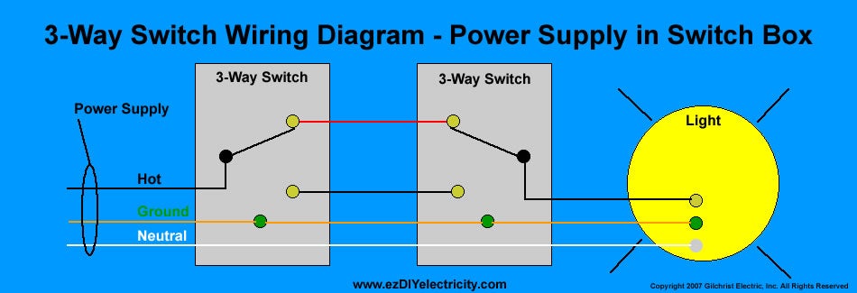
When I built my house, I had asked for all my boxes to have a neutral AND for my lights to be the last in the chain of switches, so that it would go Power --> Switch --> Switch --> Load/Light.

So, I'm trying to figure out how to wire these correctly... currently my three way wiring uses this approach:
http://www.diychatroom.com/attachments/f18/16702d1263774538-3-way-switch-installation-ti070-3w-aube-3-way-switch-wiring-diagram.jpg
16702d1263774538-3-way-switch-installation-ti070-3w-aube-3-way-switch-wiring-diagram.jpg


... to the best of my knowledge.

Switch 1's box - has Black (line/hot), Ground, and Neutral (white) and Black and Red travelers
Switch 2's box - has the travelers coming in, then Black (Load), ground, and neutral (white)

So, If you read that from Left to Right, would the appropriate way to hook up the GE switches be:

PS to Switch 1

Switch 1 - Aux switch
Black (Line/Hot) - to White/Red Aux Switch Wire
Red Traveler - to Yellow Aux Switch Wire
Black Traveler - NOT USED ?
Ground - to Green Aux Switch Wire
Neutral - NOT USED

Switch 2 - Primary Switch
Black (Load) - to Black Primary Switch Wire?
Black (Load) - to Blue Primary Switch Wire?
Black Traveler - NOT USED ?
Red Traveler - to Yellow Primary Switch Wire
Ground - to Green Primary Switch Wire
Neutral - to White Primary Switch Wire

to

Light (Load)

Am I even close to being correct? Let me know if I can provide any more details (or if I should spin this question off in its own thread.

BTW - here's the PDF to the installation manual for those of you who would like to take a better look - http://www.jascoproducts.com/support/manual-downloads/applications/DocumentLibraryManager/upload/45613-Manual-Eng.pdf

Thanks!

:::EDIT:::

Actually, I'm wondering if this would be more correct... basically hook the black traveler cable into the black hot in box 1, so at box 2 the black traveler cable is the hot needed to hook to the black wire on switch 2. Again, just trying to figure this wacky wiring system out :S


PS to Switch 1

Switch 1 - Aux switch
Black (Line/Hot) - to White/Red Aux Switch Wire
Red Traveler - to Yellow Aux Switch Wire
Black Traveler - Wired to Black (Line/Hot)?
Ground - to Green Aux Switch Wire
Neutral - NOT USED

Switch 2 - Primary Switch
Black (Load) - to Blue Primary Switch Wire?
Black Traveler - Black Primary Switch Wire?
Red Traveler - to Yellow Primary Switch Wire
Ground - to Green Primary Switch Wire
Neutral - to White Primary Switch Wire

to

Light (Load)

Just thought I'd come back after I installed the three way switch and let folks know how I accomplished it. Basically, the second assumption was correct. It's important, as other have noted, that you have the 3-way lights wired in the most simplest form - Power Supply --> Switch 1 --> Switch 2 --> light. Just as show in the diagram in my original post, or as shown in this diagram:
wiring1l.gif


DISCLAIMER: This is what worked for me. I am not an electrician, and I have no idea if the following will work in your situation. I'm not responsible for anything (good or bad) if you attempt to recreate my directions, again - I'm just documenting what worked for me. High Voltage stuff is dangerous, ask a qualified electrician for actual advice. In essence, what you are doing is converting a three way switch, into a two-way switch + a control switch.


BOX 1 - In this box, I put the Aux switch, which has a Yellow, Red/White Striped, and Green wire"
Box 1 had the following wires:
1) a Neutral that passes through (white)
2) a Hot from the power supply (Black in my case)
3) 2 Travelers (Black and Red in my case)
4) A ground (bare or green)

1) Connected the Yellow wire on the Aux switch to the Red traveler wire which goes to the second light switch box, this is the wire that is used for control
2) Connected the Red/White striped wire on the Aux Switch to BOTH the black incoming power supply wire (Common), and the black traveler wire. All three of these should be in a wire nut (this is key, and different from a traditional 3-way switch)
3) Connected the green wire on the Aux Switch to the bare/green ground wire in the box

BOX 2 - In this box, I put the Master Switch, which has Yellow, Blue, Black, White, and Green
Box 2 had the following wires:
1) a Neutral that passes through (white)
2) a load that goes to the light fixture (Black in my case)
3) 2 Travelers (Black and Red in my case)
4) A ground (bare or green)

1) Connected the Yellow Wire on the Master Switch to the Red traveler wire, this is the wire used for control
2) Connected the Black Wire on the Master Switch to the Black Traveler Wire
3) Connected the Blue Wire on the Master Switch to the Black wire that goes to the light fixture (Common)
4) Connected the White wire on the Master Switch to the neutral. In my case, the white wire was spliced in a wire nut, so I added it and put on a new wire nut
5) Connected the Green wire on the Master switch to the Bare/Green ground wire


Check this post out, it has a video and a few pointers to different wiring schemes for 3-way circuits. Hope this helps.

Knowing 3-way circuits is key, and understanding how yours is wired is very important. I would also recommend folks look at this site (which is where the graphic above is from) - http://www.homeimprovementweb.com/information/how-to/three-way-switch.htm Basically, you need Option 1 in order to use these GE 3-way switches as others have alluded.

However, while knowing how your *wiring* is accomplished for 3-way switches is valuable, these switches do not connect like a typical 3-way switch with 3 screws plus ground. The Aux Switch only has 2 connections + ground and the Master Switch has 4 Connections + Ground. But, to your point - if folks don't understand how the wiring in the wall works, it'd make figuring out the installation of these switches even more difficult since the included instructions are pretty vague and didn't even properly represent a typical wiring scenario (imho).

Good luck to anyone who installs these - it's not hard, but it does require some moderate thought and planning (and luck if you don't know how your 3-ways are wired).
 
Ok, I am really frustrated. I have my wires set up like skcocoon but in my box 2, I DON'T HAVE a NEUTRAL! There is another switch there put part of a 4 way (I think) with 4 switches controlling the upstairs hallway light. There are only 4 wires there, all hooked into that switch (looks like a double pole) and no neutral.


Box 1 :

Aux Switch (has a neutral avail and the Hot source).
Have a traveler, hot and red/white all connected together
Yellow on red wire traveler

Box 2 has the Primary (no neutral so the primary wont work.)
Black on Black Hot
Blue on Load
Yellow on Red
No home for White.

HELP!
 
OK figured out what I have.... homeimprovementweb.com/information/how-to/three-way-switch-option3.htm
With the aux on box one and primary on box 2, I can get the primary to turn on/off. The aux does nothing with the red/white on with hot and hot to the primary, yellow on the red traveler. About to give up barring any last minute advice and return these sets to radioshack.
 
An easy way is to shut off the power to the switch, disconnect the wires, disregard the coloring and use a multimeter; still being very carefull.

You know that the traveler is just that; ie: a wire between two boxes. The hot and the neutral are just that. I've noticed that the electrician in my home used white and black. If I looking inside of the fuse panel I see the whites going to the neutral block and the black wires going the each individual breaker.

Travelers are a different color; one doesn't always match another one. The wires for the ceiling fans are also different colors and same set of ceiling fans are configured with one for the lighting and the other for the fan. For my Insteon / UPB setups I've gone to virtural three ways instead of using the travelers which are just capped and taped. Sometimes for whatever reasons short cuts are done...ran out of wire so to finish the job in a timely manner circumventing code - typically the home owner won't notice because the typical homeowner doesn't "look" or replace switches or trace electrical or even open electrical panels up. On a commercial basis I've seen it both ways where I've had confidence to the point of knowing everything is OK and done to my specifications then the other way where I've literally had to spend the entire night supervising everything having to worry about "short cuts"; lessons learned because when that happened never even considered vendor for new work.

Typically the wiring of the 3 way switches are all the same whether you are using powerline or older style conventional switches (except for the virtual pieces).
 
Hi all,

Unfortunately I had a longer post before but the board squashed it since I am a new member and tried to include a link to a wiring diagram. :(

There has been a lot of useful discussion on this thread and I am hoping someone will be able to assist me.

I have a handful of GE z wave switches instaled, most in standard 2 way configuration, one in a 3 way configuration (it originally had the 80% brightness problem which I resolved by changing the AUX's common).

My new scenario/problem is this:

4 way switch install (3 switches total in this case)

There are 3 switch boxes, some switch boxes co-exist with switches with other circuits, and one switch box has ONLY this 4-way configuration in it. All boxes have neutral bundles (ONE of the boxes - one with three separate switches - has two neutral bundles, not tied together?)

At any rate, I have tried with no success to get my 4 way configuration working as intended. I am using one primary and two aux switches. No matter what I do I can only get to 80%~ brightness and it stops there. If I try it from an AUX switch, however, the lights will go to full bright momentarily while the aux switch is being HELD down. Once released the lights drop back down. I have tried converting this to a standard 3 way circuit (by wire-nutting together the items in the "middle" box - the switch that exists by itself) and that still results in the same thing, 80% brightness. Now, the part I cannot figure out is, if I even DISCONNECT the traveller at the master switch it immediately starts working at 100% brightness (obviously disabling slaves). I cannot figure out why. I have also tried leaving the traveller CONNECTED at the Master switch but capping it off at the slave switch, and it results in the same 80% brightness issue. Does anyone have any insight as to why this would be happening? I have struggled with this one for about 4 hours last night, up and down three flights of stairs, and am about to throw the towel in.. any recommendations are greatly appreciated. Thanks in advance.
 
Personally I would just do a virtual 3-4 way scenario with only one switch connected to the load and the other two switches talking to the switch with the load unless there is some reason why you cannot do this (you can use the travelers if you are short of wires). I have a similiar scenario. The second floor hallway for whatever reason has a switch outside each of the bedrooms for the second floor hallway. In total there are four switches for only 3 lights in the hallway. It'll be easier for me; cuz I don't want to play; to have one be the main connected to the load and the other's be the 2nd, 3rd and 4th virtual to the first.
 
Personally I would just do a virtual 3-4 way scenario with only one switch connected to the load and the other two switches talking to the switch with the load unless there is some reason why you cannot do this (you can use the travelers if you are short of wires). I have a similiar scenario. The second floor hallway for whatever reason has a switch outside each of the bedrooms for the second floor hallway. In total there are four switches for only 3 lights in the hallway. It'll be easier for me; cuz I don't want to play; to have one be the main connected to the load and the other's be the 2nd, 3rd and 4th virtual to the first.


I dug for some quick info on creating a "virtual" switch with the GE devices but have not found anything. Am I missing something obvious? I would be completely okay with this scenario assuming the switches stay synced properly (I have Insteon in another house and keeping the switches synced; without a controller; has been a headache!)
 
I just also looked and it doesn't look possible. You can with one GE and two wall mounted transmitters though. (but then you are buy non GE switches).
 
So the Radio Shack sale got me into automation and I've replaced 90% of the my switches. Guess I can also thank RS (maybe GE) for the opportunity to learn about wiring! The 10% remaining are the dreaded 3-ways with power coming through the light. Since the GE switches will not work in this situation, is there a z-wave switch solution? If no z-way solution is there a solution from another protocol? Thank you in advance. I have gathered valuable info over the past month from this site, but this is my first post.
 
An easy way is to shut off the power to the switch, disconnect the wires, disregard the coloring and use a multimeter; still being very carefull.

You know that the traveler is just that; ie: a wire between two boxes. The hot and the neutral are just that. I've noticed that the electrician in my home used white and black. If I looking inside of the fuse panel I see the whites going to the neutral block and the black wires going the each individual breaker.

Travelers are a different color; one doesn't always match another one. The wires for the ceiling fans are also different colors and same set of ceiling fans are configured with one for the lighting and the other for the fan. For my Insteon / UPB setups I've gone to virtural three ways instead of using the travelers which are just capped and taped. Sometimes for whatever reasons short cuts are done...ran out of wire so to finish the job in a timely manner circumventing code - typically the home owner won't notice because the typical homeowner doesn't "look" or replace switches or trace electrical or even open electrical panels up. On a commercial basis I've seen it both ways where I've had confidence to the point of knowing everything is OK and done to my specifications then the other way where I've literally had to spend the entire night supervising everything having to worry about "short cuts"; lessons learned because when that happened never even considered vendor for new work.

Typically the wiring of the 3 way switches are all the same whether you are using powerline or older style conventional switches (except for the virtual pieces).
 
ok is it possible to have only one set of neutrals on the aux side. The power on that side ( aux). With the dimmer side having no neutrals but a black wire going to light. Then how do you wire this thing. Should I just move the dimmer over to the aux side
 
Hello everyone.  Sorry to resurrect an old post, but I find myself in need of help in this area.  I've read through this post and others and I'm still a bit unsure of how to proceed.
 
Here's the situation:
 
I'm attempting to install a z-wave 3-way dimmer kit in place of existing 3-way switches.  The model that I'm installing is a 46512 and a 46510.  This will control a chandelier in my dining room.  There's one switch in my kitchen in a box that has three other switches and one in the dining room in a box that has two other switches.  The hot wire (line) is in the box in the kitchen.
 
Each switch that I removed had a ground wire, two black wires and a red wire.
 
I verified which black wire was hot in the kitchen switch box, and I connected that to the "line" terminal on the 45612.  I connected the other black wire to the "load" terminal.  I connected the red wire to the "traveler" terminal and the bare wire to the "ground" terminal.  
 
In the dining room box, I tied the two black wires together and capped them with a wire nut.  I connected the red wire to the "traveler" terminal on the 45610 and I connected the bare copper wire to the "ground" terminal.  I then fished into the back of the switch box and found the white neutral wire bundle.  It has two white wires - one that goes back to the kitchen switch box and one that goes to the chandelier.  I added another white wire to this bundle and connected it to the "neutral" terminal on the 45610.  It is interesting to note that the white ground wire in the kitchen switch box is tied into a large bundle of neutral wires from the other switches in that box.  I see that the instruction manual mentions that I should separate bundles like this, but I'm not really sure how to do that.  I suspect that this is my issue.
 
As it stands now, the light can be correctly controlled with the 45612 in the kitchen switch box.  It has on/off functionality as well as dimming functionality.  It was easily connected to my z-wave system.  The 45610 aux switch, on the other hand, is not working properly.  It will not turn the chandelier on or off.  If the chandelier is on, then it will cause it to flicker when held in the "up" or "on" position.  I did try switching the switches to the other switch box, but they wouldn't work at all in that configuration.
 
Any help would be greatly appreciated.  I plan to call my electrician tomorrow if I can't sort this out.
 
Thanks!
 
Dennis
 
Additional notes.
 
I was able to successfully switch the 45610 to the kitchen box (where the hot wire is located) per the instructions.  The 45612 is now in the dining room box, and it works perfectly.  The 45610 still doesn't work.  I'm at a loss as to where to go next.  
 
Back
Top