charliebarns
Active Member
Hey guys,
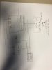
I'm trying to figure out the wiring of Elks Water Shutoff Valve to my Omni Pro II. There are 4 wire coming off the WSV:
Green (Value Status). When the value is closed this produces 12Vdc output.
Red (Valve Close), says connect to normally closed relay output. When energized with 12Vdc this closes the value.
White (Valve Open) says connect to Normally open relay output. When energized with 12Vdc this opens the valve.
Black (Negative).
Any idea how to translate this to the Omni Pro II so I can monitor the value status, open it or close it?
Thanks
CB