Potentiometer question

Ira

Active Member
I admit I'm not much of an electronics guy, so what am I missing here?

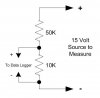
I am getting a data logger that logs DC volts in the 0 to 2.5vdc range. I want to monitor a generator battery with it because I'm having intermittent problems with battery's voltage. The battery is a typical group 26 auto battery. I'm assuming that the battery voltage will never go above 15vdc, so I want 0-15vdc to be reduced to 0-2.5vdc for the logger. The manufacturer pointed me to this FAQ entry on their website to find out how to build a voltage divider. Essentially, the formula it has says I need a 50k ohm resistor in series to drop the voltage from 15 to 2.5.

I wanted to test things before hooking up the logger, so I got a 50k ohm potentiometer. I tested the battery voltage with a multimeter first, and it showed 13.44vdc. I then clipped the pot in series between the battery's positive post and the multimeter's positive lead, and connected the negative multimeter lead to the battery's negative post. When I turned the pot, the voltage only varied from 13.44 to 13.37. I tried it with a 100k ohm pot and that resulted in double the reduction -- from 13.44 to 13.30. So according to those numbers, I would need something like a 10 megaohm resistor to drop 15v to 2.5v.

So can someone school me on this?

Thanks,
Ira
 
A voltage divider typically uses two resistors, which the ratio between the two as the key to the output voltage.
http://www.raltron.com/cust/tools/voltage_divider.asp
With 15VDC in and a desired 2.5 VDC out, r1 could be 1000 and r2 could be 200.

You could use your 100k pot as R1 and try to dial up 20000 ohms on your 50k pot.

You could also hook the outer two connectors of your potentiometer to the battery. Then connect your voltmeter to one of the end connectors and the middle connector of the pot. Then just turn the pot until you get 2.5V or less. This lets you play with what you have, but isn't the most accurate as all your data is garbage if the pot gets bumped.
 
Basically you want a voltage divider using two resistors. The total current the resistors pull on the overall circuit should be very small as not to draw the battery source down.

You want to go from 15 volts to 2.5 volts or an overall ratio of 6.

If I pick a 10K resistor for the 2.5 volt side of this ratio I would need to incorporate a 50K resistor to achieve this same ratio (60K to 10K ratio is 6).

So use the schematic below and 'measure' the voltage across the 10K resistor with your data logger. Just be aware that you will have to develop a slope/intercept formula to obtain a true "engineering unit" value for the "15 volt" measured source.

If you need any additional help refer to my Guide on Analog to Digital Converters.
 

Attachments

  • ratio.jpg
    ratio.jpg
    15.1 KB · Views: 5
A voltage divider typically uses two resistors, which the ratio between the two as the key to the output voltage.
http://www.raltron.com/cust/tools/voltage_divider.asp
With 15VDC in and a desired 2.5 VDC out, r1 could be 1000 and r2 could be 200.

You could use your 100k pot as R1 and try to dial up 20000 ohms on your 50k pot.

You could also hook the outer two connectors of your potentiometer to the battery. Then connect your voltmeter to one of the end connectors and the middle connector of the pot. Then just turn the pot until you get 2.5V or less. This lets you play with what you have, but isn't the most accurate as all your data is garbage if the pot gets bumped.

Thanks for the info. I played around with it using an 8.4vdc wall wart (too dark to mess with the battery). With what you said and the simple diagram on the Ralston website, I was able to get it to work in both configurations you suggested.

Thanks,
Ira
 
Basically you want a voltage divider using two resistors. The total current the resistors pull on the overall circuit should be very small as not to draw the battery source down.

You want to go from 15 volts to 2.5 volts or an overall ratio of 6.

If I pick a 10K resistor for the 2.5 volt side of this ratio I would need to incorporate a 50K resistor to achieve this same ratio (60K to 10K ratio is 6).

So use the schematic below and 'measure' the voltage across the 10K resistor with your data logger. Just be aware that you will have to develop a slope/intercept formula to obtain a true "engineering unit" value for the "15 volt" measured source.

If you need any additional help refer to my Guide on Analog to Digital Converters.

Thanks BSR,

A simple diagram like yours and the one on the Raltron helps a lot. Wish the manufacturer had one, although I should have just googled it.

Ira
 
If you want to increase accuracy of your "equation" actually measure the voltage of the 15 volt source (with a multimeter), then immediately measure the voltage across the 10K resistor and use that as your ratio numbers.
 
But... but... but...
Why not just use the potentiometer as-is. Apply power and just turn the shaft until you get 2.5 V.
 

Attachments

  • potentiometer.jpg
    potentiometer.jpg
    22.7 KB · Views: 3
Yours works fine Lager.
Two big points though; I think the original post was connected as a voltage divider with the pot and the internal resistance of his multimeter.
Secondly, if the pot is linear taper it would work great, audio taper, not so great,
 
But... but... but...
Why not just use the potentiometer as-is. Apply power and just turn the shaft until you get 2.5 V.
Because the 2.5V output would be a max scale reading IF it had 15VDC input, which is the assumed max limit. Without a 15VDC power source, he won't be able to get the 2.5V output. But since the whole thing is ratio dependent, with any known available input voltage, you should be able to rotate the pot to get the desired output voltage sine the voltage divider is linear.
 
But... but... but...
Why not just use the potentiometer as-is. Apply power and just turn the shaft until you get 2.5 V.

It would have helped if the OP (me :rolleyes: 
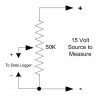
) knew what he was doing. I bought the pots to play around with so that I could understand how to hook things up when I got the data logger and the appropriate resistors. Since I wired up the pot incorrectly (been a really long time since I've done any of this stuff and I didn't have a diagram to go by at the time), it did not work. I've set up all of the suggestions in this thread, and all of them work. The pots are linear taper.

I also emailed the manufacturer to get his recommendations for resistor values. Using BSR's diagram as a reference, the manufacturer's tech support guy recommends a 33k ohm resistor and a 6.8k ohm resistor (which is not quite a 5:1 ratio) with a 0.1uF cap (which he says will "help with impedance", whatever that means) wired in at the same place as the data logger's leads. He said that this data logger setup will draw less than 1mA. The logger will be sampling once every second.

Thanks for the help.
Ira
 
A variable pot would work (I hope my original post wasn't interpreted as discrediting that idea) but (as I believe Wayne stated) if the pot moves, your ratio would be off.

I like a hard value resistor and as I mentioned above, actually measure the ratio voltages (source and voltage across the 'data logger' resistor) so I get a more accurate ratio number than a 'calculated' value. This ratio should never change, which is what you want for long term data collection.
 
I like a hard value resistor and as I mentioned above, actually measure the ratio voltages (source and voltage across the 'data logger' resistor) so I get a more accurate ratio number than a 'calculated' value. This ratio should never change, which is what you want for long term data collection.

I agree. There shouldn't be any need to vary the resistors once the correct pair is chosen. Using a pot would open up the possibility of someone accidentally changing the voltage. I guess cranking the pot up to allow a hgh enough voltage thru could maybe damage the data logger. Wonder if I should look into some kind of "voltage limiter" circuit it there is such a thing that could be easily added without affecting anything else.

Ira
 
Looks like this project is scrapped for the next four years. A few days ago, the generator manufacturer warned me that this project would void my warranty. Since I've got an extended warranty, it's covered for about four more years.

The manufacturer agreed that the things I wanted to do (monitor/log battery voltage, attempts to start the engine, engine oil pressure, and engine coolant temperature) would not negatively afffect the generator. The day before, they even said I could do all of them. Then they called back and said it would go against the UL listing's requirements. That in itself would void the warranty.

The sad part is that two of the things I wanted to do (battery voltage and starter attempts) were mainly to help them diagnose an intermittent problem that has been going on since last November. Sometimes the generator won't start on a power outage or for weekly exercise, and it throws a low voltage fault lite.

Ira
 
Back
Top