Mr Spock
Active Member
I'm testing the control of my first Somfy shade motor to my OP II panel while the motor sits on my desk. Its the ST30 IWT RS485 (model number 1000658). I can't seem to get it to move. I've read the excellent write up from Relleum on how to configure it, but nothing. I'm seeing three ways I may be getting this wrong, but first let me state what I've done.
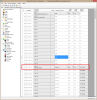
1) I used the ILT2-ST30 address configuration tool to convert my IWT motor's address of 0616BA to the ILT address of 45-E9-F9. This is shown in the screen shot from Dealer PC Access Units.
2) Under Expansion/Serial I've set serial port 1 to Somfy ILT with a baud rate of 4800.
3) I've confirmed 24VDC of the correct polarity at the motor's pins.
4) The Somfy documentation says the motor's control wires are red = + and black = -. Wikipedia says for RS485 that + = B and - = A. Just to be sure I tried it both ways.
What I'm not sure about:
1) I wired up a cable to connect the panels serial port 1 to the Somfy 10 motor distribution board connector P1. Serial port 1's jumper is set to RS485. The 4P4C connector is at the OPII and the 8P8C connector at the distribution board. I followed the picture from Relleum, but I'm having some doubts its correct. The OPII serial connectors have 6 pins and I've only got 4. I know only 2 wires are used for RS485, but not sure a 4P4C connector will put them in the right location.
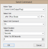
2) Sending commands from the OPII panel. I'm using the Send Command function as shown below. This does not seem designed for sending commands to a shade motor. Is ON up and OFF down? Am I correct in testing it this way?
3) I'm assuming the motor should just start turning if activated correctly, even though its not installed with a shade. Am I correct in assuming this?
Thanks.
1) I used the ILT2-ST30 address configuration tool to convert my IWT motor's address of 0616BA to the ILT address of 45-E9-F9. This is shown in the screen shot from Dealer PC Access Units.
2) Under Expansion/Serial I've set serial port 1 to Somfy ILT with a baud rate of 4800.
3) I've confirmed 24VDC of the correct polarity at the motor's pins.
4) The Somfy documentation says the motor's control wires are red = + and black = -. Wikipedia says for RS485 that + = B and - = A. Just to be sure I tried it both ways.
What I'm not sure about:
1) I wired up a cable to connect the panels serial port 1 to the Somfy 10 motor distribution board connector P1. Serial port 1's jumper is set to RS485. The 4P4C connector is at the OPII and the 8P8C connector at the distribution board. I followed the picture from Relleum, but I'm having some doubts its correct. The OPII serial connectors have 6 pins and I've only got 4. I know only 2 wires are used for RS485, but not sure a 4P4C connector will put them in the right location.
2) Sending commands from the OPII panel. I'm using the Send Command function as shown below. This does not seem designed for sending commands to a shade motor. Is ON up and OFF down? Am I correct in testing it this way?
3) I'm assuming the motor should just start turning if activated correctly, even though its not installed with a shade. Am I correct in assuming this?
Thanks.