pete_c
Guru
Installed / tested 30th of March, 2022 2000 c
This are known as Virage or generic KS-7012.
Hardware required / used (purchased from Amazon) for JTAG
1 - DSD TECH USB to TTL Serial Adapter with FTDI FT232RL Chip Compatible with Windows 10, 8, 7 and Mac OS X $12.49 USD * note this is my favorite one out of many I have used.
2 - EDGELEC 120pcs Breadboard Jumper Wires 20cm Wire Length Optional Dupont Cable Assorted Kit Male to Female Male to Male Female to Female Multicolored Ribbon Cables $6.99 USD
3 - Laptop with Wireless and network port (personally use Ubuntu Linux). Any old laptop will do or any old desktop will do.
4 - screwdriver set - here is a cheapo set on Amazon - Mini Screwdriver Set with 42 Bits, VCELINK 45 in 1 Small Precision Screwdriver Bit Set, Magnetic Tiny Screwdriver Kit with Tweezers & Extension Shaft for Laptop, PC, Phone, Computer, Game Console $12.99 USD
5 - old computer cord - cut the female end off and strip the end wires. You will only need the black and white wire for testing.
Software Required
1 - Tasmotizer (personally use Linux here). Very nice GUI. I used to use command line Python to do this a few years back.
NOTE: Tuya-Convert (OTA) does not work with these switches
Virage Labs VirageDimmer
Purchased these in bulk last year for around $13 each.
Virage Labs is now closed. I did test their Tasmota firmware and it did work when I tested it.
Virage Labs
VirageLabs created a proprietary HA add on which worked when I tested it.
Dimmer Instructions are attached.
Original custom Tasmota Virage Dimmer firmware is also attached.
Firmware
Currently utilizing most current version of Tasmota with these switches.
This is a revisit here relating to taking them apart and programming them with Tasmota.
Pictorial will be posted here for taking them apart. It is much more difficult to take them apart than to update them with Tasmota.
Taking apart the Virage KS7012 switch for JTAGing with Tasmota. (total 10 tiny screws optionally or 6 if you do not remove main board).
1 - remove two screws on the back cover.
2 - remove cover and heat sink and flip up regulator
3 - remove 4 corner screws and lift off back cover
4 - there are small little tabs connected to switches, remove these.
5 - remove 4 screws holding faceplate board and remove board. (optional and easier for me)
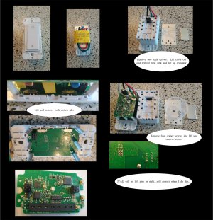
Tiny pieces of plastic switches / a couple of springs inside of the switch.
JTAG and Upgrading firmware to Tasmota - solderless methodology
1 - connect left side pins VCC, Ground, RX and TX.
2 - connect gpio 0 (I00) to ground
3 - run Tasmotizer
4 - plug in and auto connect to board
5 - upgrade firmware to latest Tasmota Bin.
6 - unplug USB TTL stick and disconnect GPIO 0 from ground
7 - power up board with USB TTL stick (I left the RX/TX cables in place)
8 - you will see the board boot up in AP mode
9 - connect to AP mode of Tasmota and configure it to connect to your home AP
10 - it will reboot and get a DHCP address from your home LAN
11 - connect to the IP and you will see Tasmota unconfigured.
12 - put it back in the switch case...and make sure there are no extra screws left when you are done.
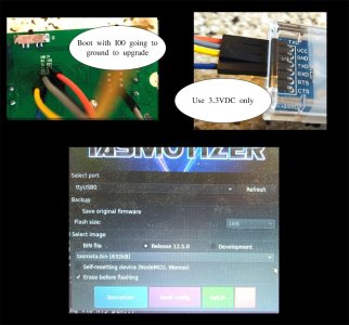
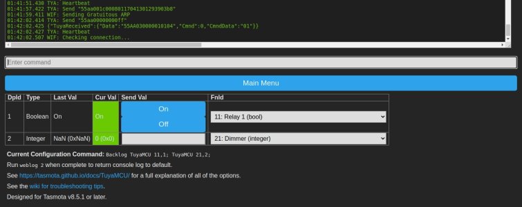
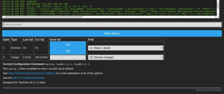
Configuration of Tasmota Tuya KS-7012 (Easy Button way)
1 - using the cut computer cord attach it to the black and white leads using wire nuts. Also put wire nuts on all of the free leads from the switch. Be carefull. Plug the computer cable in to a power strip.
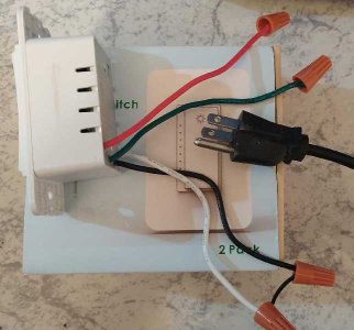
2 - Go to IP of new device. Here just looked at the firewall to look for new device in the DHCP list.
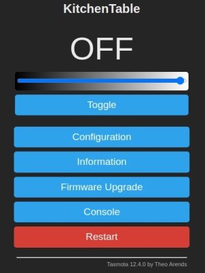
New unconfigured device here is named: tasmota-1E2278-0632 with IP of 192.168.244.252
Continued on next post.
20th of April, 2023 - Updating this post via my back up Internet (T-Mobile LTE modem) which is working fine today as XFinity will probably be down all day. The Ooma and Obi VOIP boxes work fine via the T-Mobile LTE modem (connected to PFSense).

This are known as Virage or generic KS-7012.
Hardware required / used (purchased from Amazon) for JTAG
1 - DSD TECH USB to TTL Serial Adapter with FTDI FT232RL Chip Compatible with Windows 10, 8, 7 and Mac OS X $12.49 USD * note this is my favorite one out of many I have used.
2 - EDGELEC 120pcs Breadboard Jumper Wires 20cm Wire Length Optional Dupont Cable Assorted Kit Male to Female Male to Male Female to Female Multicolored Ribbon Cables $6.99 USD
3 - Laptop with Wireless and network port (personally use Ubuntu Linux). Any old laptop will do or any old desktop will do.
4 - screwdriver set - here is a cheapo set on Amazon - Mini Screwdriver Set with 42 Bits, VCELINK 45 in 1 Small Precision Screwdriver Bit Set, Magnetic Tiny Screwdriver Kit with Tweezers & Extension Shaft for Laptop, PC, Phone, Computer, Game Console $12.99 USD
5 - old computer cord - cut the female end off and strip the end wires. You will only need the black and white wire for testing.
Software Required
1 - Tasmotizer (personally use Linux here). Very nice GUI. I used to use command line Python to do this a few years back.
NOTE: Tuya-Convert (OTA) does not work with these switches
Virage Labs VirageDimmer
Purchased these in bulk last year for around $13 each.
Virage Labs is now closed. I did test their Tasmota firmware and it did work when I tested it.
Virage Labs
VirageLabs created a proprietary HA add on which worked when I tested it.
Dimmer Instructions are attached.
Original custom Tasmota Virage Dimmer firmware is also attached.
Firmware
Currently utilizing most current version of Tasmota with these switches.
This is a revisit here relating to taking them apart and programming them with Tasmota.
Pictorial will be posted here for taking them apart. It is much more difficult to take them apart than to update them with Tasmota.
Taking apart the Virage KS7012 switch for JTAGing with Tasmota. (total 10 tiny screws optionally or 6 if you do not remove main board).
1 - remove two screws on the back cover.
2 - remove cover and heat sink and flip up regulator
3 - remove 4 corner screws and lift off back cover
4 - there are small little tabs connected to switches, remove these.
5 - remove 4 screws holding faceplate board and remove board. (optional and easier for me)

Tiny pieces of plastic switches / a couple of springs inside of the switch.
JTAG and Upgrading firmware to Tasmota - solderless methodology
1 - connect left side pins VCC, Ground, RX and TX.
2 - connect gpio 0 (I00) to ground
3 - run Tasmotizer
4 - plug in and auto connect to board
5 - upgrade firmware to latest Tasmota Bin.
6 - unplug USB TTL stick and disconnect GPIO 0 from ground
7 - power up board with USB TTL stick (I left the RX/TX cables in place)
8 - you will see the board boot up in AP mode
9 - connect to AP mode of Tasmota and configure it to connect to your home AP
10 - it will reboot and get a DHCP address from your home LAN
11 - connect to the IP and you will see Tasmota unconfigured.
12 - put it back in the switch case...and make sure there are no extra screws left when you are done.

Configuration of Tasmota Tuya KS-7012 (Easy Button way)
1 - using the cut computer cord attach it to the black and white leads using wire nuts. Also put wire nuts on all of the free leads from the switch. Be carefull. Plug the computer cable in to a power strip.

2 - Go to IP of new device. Here just looked at the firewall to look for new device in the DHCP list.
New unconfigured device here is named: tasmota-1E2278-0632 with IP of 192.168.244.252
Continued on next post.
20th of April, 2023 - Updating this post via my back up Internet (T-Mobile LTE modem) which is working fine today as XFinity will probably be down all day. The Ooma and Obi VOIP boxes work fine via the T-Mobile LTE modem (connected to PFSense).
Attachments
Last edited:

