Measuring Amps with CAI webcontrol

The CST-1020 looks to be similar to the CR3110 - a simple current transformer of about 1000:1 ratio.  Whatever the AC current in the primary you get 1/1000 of that in the secondary.  Another somewhat similar part is the CSE187L (used in the open energy monitor project). 
 
The ACS712 has 1/2 Vcc at no current so it can run from a single supply and measure both polarities of current.  It also makes connecting it to a single supply analog circuit like a microprocessor a/d converter easy.  Claiming it was designed that way to overcome using a diode on the output is a stretch although it should work, especially with calibration.  But if you want high accuracy you need to think about the variation of the diode voltage drop with temperature, etc.
 
Here's a link about current transformers and DC that google turned up:
https://www.crmagnetics.com/Products/Assets/ProductPDFs/Precision%20Rectifier%20Circuit%20for%20CT%20Signal%20Conditioning.pdf


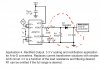
The CR3110 circuit given earlier has the diodes before the load or "burden" resistor.  The signal at this point is a current not a voltage to avoid the diode drop issue but as noted in the link the current transformer may not support the additional voltage.  I think the CSE187L would be more likely to work given the conventional core but I don't know for sure.  Make sure you don't use any current transformer without the load resistor - it will generate high voltages and could damage things.
 
The startup current on an induction motor can easily be more than twice it's rated running current.  Before using the ACS712 solution I would want to check if it could handle over currents.  High transient over currents shouldn't be an issue with the current transformers.
 
CAI_Support said:
Rectifier has 0.6V barrier voltage. If the AC signal is less than that, you will not read anything. The ACS712 is designed to have zero volt at 0.5 * Vcc to overcome this problem.  Its output can be bipolar or unipolar.
 
I think could add rectifier and  large enough filter capacitor to try, get a calibrated curve by measuring few know current.
 
Bridge rectifier has *two* diode drops though, so around 1.2V.
If the device output is 2.5V +/- 100mV/A you have -13A before you're in trouble, and output will be offset by 1.2V (approx)
so 0V = -13A, 1.3V=0A, (5V-1.2V = 3.8V) = +25A
If you are happy reading 0-3.8V on a 0-10V input (or around 0.1A/bit theoretical resolution, less jitter etc) then fine - but the thermal drift of the diodes will also come into play (as diodes get warmer and cooler your "zero" is going to drift, quite a bit!)
 
I don't understand how a bridge rectifier would work with the acs712.  That device is always positive voltage.
 
I do understand how it work with one of the regular current transfomers.  But the diodes cutting down the voltage would seem to be a problem.
 
JimS said:
 
Yes, this seems to be addressing exactly what I need.  Motor control using current as the indicator of motor load.
 
Now I just have to figure out all the details.  
 
The zener diodes?  Are they just there to prevent an overvoltage?
 
The details on which resistors, which lm324.  Also there appears to be a capacitor in there as well.
 
rossw said:
Bridge rectifier has *two* diode drops though, so around 1.2V.
If the device output is 2.5V +/- 100mV/A you have -13A before you're in trouble, and output will be offset by 1.2V (approx)
so 0V = -13A, 1.3V=0A, (5V-1.2V = 3.8V) = +25A
If you are happy reading 0-3.8V on a 0-10V input (or around 0.1A/bit theoretical resolution, less jitter etc) then fine - but the thermal drift of the diodes will also come into play (as diodes get warmer and cooler your "zero" is going to drift, quite a bit!)
Ross,
 
you are correct there is no need for bridge rectifier in this case.  I assume the current change is not that frequent, in most case delay for a second or two seconds is not that critical. If that is the case, then ACS712 output with a single rectifier with filter capacitor and load resistor will be good enough for range of 1.9-4.4V output range. If full range measurement is needed, then you will need to have amp terminal board to help boost the analog input to full range.
 
Rectifier will prevent the capacitor discharge through ACS712, but do allow ACS712 to charge the capacitor.  ACS712 max load is 4.7K, If put a 10K as load of the rectifier, and 33uF capacitor to filter the 60Hz noise, it may work without sample and hold IC.
 
From ACS712 manufacture datasheet page 12, it showed this schematics for connecting to AD converter:(see attached picture)
The eBay item actually has 1K resistor from pin7 already, just add another 1K and 10K to ground, then add D1 and C1, you could use it with WebControl ADC directly.
 

Attachments

  • ACS712toADC.jpg
    ACS712toADC.jpg
    88.2 KB · Views: 32
Please note it says in the datasheet that R1 can be omitted. In that case, Just have a diode and C1 filter then to WebControl analog input.  I would suggest to add 10K resistor in parallel to C1, since you want to measure the current change, added 10K resistor will help discharging the voltage on C1.
 
CAI_Support said:
From ACS712 manufacture datasheet page 12, it showed this schematics for connecting to AD converter:(see attached picture)
The eBay item actually has 1K resistor from pin7 already, just add another 1K and 10K to ground, then add D1 and C1, you could use it with WebControl ADC directly.
 
Do I understand that this setup will rectify AC input and give a steady state DC output voltage indicative of the AC input current?
 
And I see nothing on the ACS PCB that is a "filter" output.
    EDIT: OK, I think that diagram is for the actual chip, not the pcb with the chip on it.  But still not sure if this is going to output a steady state DC voltage when you input an AC current.
 
Since you posted the question, we ordered one of this sensor so that we can play with it. If you look the picture, the one on top near Gnd pin is the filter capacitor ACS712 datasheet mentioned. The one near bottom is another filter capacitor for the Vcc power line.
 

Attachments

  • Image3.jpg
    Image3.jpg
    148.1 KB · Views: 3
By look this microscope picture, I see the output connects directly to the Out pin, the 1K resistor is for limiting the current for power LED.  So you do want to add an 1K resistor from Out to rectifier diode.
 

Attachments

  • Image5.jpg
    Image5.jpg
    142.9 KB · Views: 2
I still don't see any of this stuff taking a value that runs a sine wave centered at 2.5 volts and turns it into a steady voltage output indicative of the RMS value.
 
What its output is 60Hz AC signal from ACS712, through a diode being rectified as DC, with additional C1 capacitor to smooth out the AC jitter, just like old transformer power supply.  The diode they specified is a switching signal diode, which has very small leakage current.  If the capacitor is big enough, the DC voltage on the capacitor will reach very close to the peak of the rectified AC.
 
You will need to add another resistor like I mentioned before to "drain" the voltage from the capacitor, so that when primary side AC current reduced, its AC voltage output will also reduce proportionally, the rectified DC without load resistor will remain high.  You will need to adjust this resistor to discharge the DC voltage on the ADC input fast enough to follow the AC change. 
 
We don't have the !N4448 diode in our lab. We just ordered some, once they are coming, we can run a test to see how that working out.   Regular rectifier diode has too much leakage current. 
 
Back
Top