apostolakisl
Senior Member
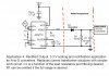
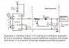
CAI_Support said:What its output is 60Hz AC signal from ACS712, through a diode being rectified as DC, with additional C1 capacitor to smooth out the AC jitter, just like old transformer power supply. The diode they specified is a switching signal diode, which has very small leakage current. If the capacitor is big enough, the DC voltage on the capacitor will reach very close to the peak of the rectified AC.
You will need to add another resistor like I mentioned before to "drain" the voltage from the capacitor, so that when primary side AC current reduced, its AC voltage output will also reduce proportionally, the rectified DC without load resistor will remain high. You will need to adjust this resistor to discharge the DC voltage on the ADC input fast enough to follow the AC change.
Except my understanding is that the output is never negative, so I diode won't rectify it. As the specs report, the signal is 2.5v at 0 current. As current moves one direction, the value goes up toward 5v, as the current reverses the output goes down toward 0v. But it is always between 0 and 5v. In other words, a sine wave shifted upward where the "0 crossing" actually occurs at 2.5v.