Alarm Panel connect to UPB Input/Output Module

BPet

Member
I have an Ademco, FA168CPS, First Alert Professional Security Systems standard security system put in my home by the home builder 5 years ago. Is there a way to connect a UPB Input/Output module somewhere to the Security Panel such that when the alarm is 'armed' it would trigger the Input/Output module? So, then whenever we 'arm' the alarm, I would have an UPB event trigger that I could use to automate other items...like watch for motion sensor triggers etc. (to clarify, so I'm looking to have the trigger when the system is 'armed' not when the Alarm sounds etc.)
 
Thanks in advance for any help that anyone can provide...
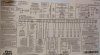
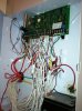
 
You need to find out if you have any relay outputs available on your system.  If not, I believe they do have a relay board for it.  You can then program a relay output to trigger the SAI UPB IO module.
 
I just looked at the board, and at the diagram stuck to the inside of the housing...I'm seeing stars :)   There is so much stuff, I can't tell if I have a relay output?  Is there a way that I can post a picture to this message?
 
Your account has been upgraded, you should be able to post pictures/attach images now.
 
I have uploaded an image of the alarm panel diagram....can you tell if it has a relay so that I can connect the Input/Output module to trigger when I 'arm' the alarm?
 

Attachments

  • firstalert.jpg
    firstalert.jpg
    141.3 KB · Views: 25
Here is a copy of the installation manual I found: http://www.alarmhow.net/manuals/First%20Alert/FA148CP/FA148CPSIA%20v6%20Installation%20Manual.pdf
 
From both your picture and the manual, it appears that there are 2 on board triggers.  Note that these are "triggers", not relays.  This means you may need to attach a relay to these trigger connections to use them.  Additionally, there is a #4204 relay board available that has 4 relays on it.
 
Look at the section in the manual on triggers and also check out the section on keyswitch arming.  The keyswitch arming has an example of using LED's off the triggers for showing armed/disarmed status and discusses the programming option to set it.  You will do a similar type setup to program them and wire them to the IO module. 
 
I looked at the manual, I do not even see the 8 Pin Trigger Connector?  Do you see it?
 
Thanks again!  :)
 

Attachments

  • sIMG_0245.JPG
    sIMG_0245.JPG
    109.5 KB · Views: 14
Terminals 4 5 6 7.
See the top middle image of 2 boxes? The top box, bottom paragraph. You can add relays, none on-board.
 
What Frunple refers to above is for adding relay boards.
 
The two built in trigger outputs are on the 8 pin strip in the center of the board above the screw terminals.
 
Look at your first picture of the label where it says "8 PIN CONNECTOR" near the top.  It is the small pin connector that it is referring to.  Pins 1 & 5 are the output pins.
 
I see the 8 pin connector now, thanks!  So, does that mean that all that I have to do is to connect leads from output 1 and 5 to the UPB Input/Output module and then when the alarm is "armed" it will trigger an event in the Input/Output module?
 
Another though, provided by Electron, maybe the Pulseworx PW-513 http://www.pulseworx.com/PW513_.htm would work so that the entire alarm system would send UPB events?  Then, whenever my current motion detectors were triggered, it would give me a UPB event :) and so I could just add a few wireless motions to my existing system :)  I see all the talk of X10 in the Alarm Panel manual, but its pretty confusing to me :)
 
It looks to me like that should work.  The manual is confusing though and refers to a special power transformer that should be used, but then for Canada, it shows just using the PSC04 (Same as PL-513) for sending commands.  Looks to me like you could use the UPB PW-513 and wire it directly to the connections as outlined for Canada.  The difference is likely for UL certification.
 
I emailed Pulseworx to see if they can confirm that this will work by simply wiring the PW-513 to that 8 pin connector...Thanks for the input
 
JonW, do you think it would be as simple as connecting to that 8 pin connector and then I would see the alarm system window sensors, motion sensors etc. in the UPB Upstart software? or do you think i would have to do any programming on the Alarm System Panel?
 
Um......No. :wacko:  That would only work in a perfect world.  I think you need to do some studying on the different components involved and what needs to be setup with each one.
 
You will need to wire the PW-513 to the panel, then you will need to program the panel (as if it had X-10 connected) and tell it what kinds of events will trigger what X-10 house/unit codes.  You'll then need to add the PW-513 to UPStart and program it on how to react to each of the X-10 codes it expects to see.  When I say react, I mean what UPB links will it transmit for each X-10 code it sees.  You will then need to program your UPB devices to act accordingly on these UPB links.
 
Back
Top