EOL Resisters Use and Placement

That's a very good point, putting the resisters EOL would be a pain to change out if you changed the security panel. I suspect that I won't be changing the security panel, so I think I'll still put them EOL. But just in case I'll video the the install before the sheetrock goes up.

That is also a good reason to put the resister close to the last switch with enough loose wire to allow extraction of the switch (even if you break it), and get at the resister. Anyone have experience with having to change out resisters?
 
I don't think you would have to change the EOL for a new panel. You could always put another in series or parallel (inside the panel door) to have the new panel see the value it is looking for. Heck, that would be even more confusing for an alarm hacker. Just calculate what resistance is needed to achieve the new value.
 
DavidL said:
I don't think you would have to change the EOL for a new panel. You could always put another in series or parallel (inside the panel door) to have the new panel see the value it is looking for. Heck, that would be even more confusing for an alarm hacker. Just calculate what resistance is needed to achieve the new value.
How would this work? I assume that if you need to increase resistence, then you would add a resister to get to the total resistence you need. How would you add a resister if you needed to decrease the resistence? :angry:

I assume based on your post this is why you mention putting in the resister in series or parallel.
 
When adding a resistor in parallel, the net resistance goes down.

http://physics.bu.edu/py106/notes/Circuits.html
http://www.radio-electronics.com/info/circ...in_parallel.php

But, I think you would have to test this, because in a worst case scenario, the new panel might not be happy with the new (local) resistor in circuit all the time. It might not detect enough of a difference between the resistor pair and the single resistor to trip the alarm. If I knew more about typical EOL resistor values I could play with the numbers, as this might all be irrelevant.
 
Just in case anybody is confused, in BSR's first two drawings, when he said "zero ohms" (short circuit), he meant to say "infinite ohms" (open circuit). :angry:

BSR Edit: Thanks for catching this error Wayne!! I corrected the above drawing.
 
You should not have to remove drywall to get to the contacts. If you remove the moulding around the window/door, you should be a be able to get to the contact and EOL.

Just in case anybody is confused, in BSR's first two drawings, when he said "zero ohms" (short circuit), he meant to say "infinite ohms" (open circuit).
What can you expect from the poor guy? He has so much information stored in his head, such as the flying speed of an english sparrow, that he sometimes gets the fact confused. :angry:
 
aaaaaaaaahhhhhhhhhh, I hate it when I say one thing and mean another!! I will correct it in a minute!

Thanks for correcting this!! That's what I get for doing things in a hurry. :angry:
 
Hi all. I’m new to all this home auto stuff and I’m glad I found this site.
I am installing an alarm myself now, my first time, and I have the option to install the EOL transistors.
As you can see by my username I am a nit wit when it comes to tech.
Can one of you very knowledgeable and helpful people tell me exactly where to place the transistor?
As an example lets say I have a surface mount window sensor..
Is it to the + lead on the sensor then attach that to the wire? I’m pretty lost and frankly yes you need to explain it to me like you would a ten year old. Though today I guess a 10 year old would know how to do this.
 
Well this is an easy answer.

There are NO transistors, only resistors!

Actually there should be no polarity when it comes to contact closures that these magnetic sensors offer. Someone correct me if I am wrong, but it does not matter what contact the EOL resistor is on, just as long as it is in "series" with the loop.

If you need any more detail let me know, or refer to my drawing above.

Regards,

BSR

Also, welcome to Cocoontech. You may also want to browse through my How-to on installing your security system.
 
Sorry to bump this up from a few months ago, but I figured it'd be better to do that than to start a whole new thread.

I'm installing an M1G and do not understand this resistor business. I watched the video, where resistors were placed in the panel, then I read here that is not what is supposed to be done. 'TheNitWit' pretty much posted the question I'm looking to have answered. BSR, you answered it, but ... I'm sorry, I do not understand. I'm not an electrician, so if someone could, in the most simplest terms, just tell me what to do with these resistors... I'd greatly appreciate it.

"but it does not matter what contact the EOL resistor is on, just as long as it is in 'series' with the loop."
ok... I think I understand "part" of this. The resistor can be on any contact.
"in series with the loop" ... What does that mean?

So the resistor should be wired to a contact... The manual says the "furthest most remote end of the detection wiring". Does this mean the contact that is physically the furthest one from the panel?
And I'm guessing the way to wire it is... one leg to the each of the two wires on the contact.

I read the EOL write-up in the glossary, but something doesn't make sense to me. If I connect the resistor to a window sensor at the back of the house, then drive a nail into the wire for the contact at the front door, how would the resistor at the window help?

Sorry for all the stupid questions, but I just wanna get this system installed correctly and with what I'm reading here, you guys are talking way over my head... :D
 
Well, first off, in my opinion, you have to be really paranoid that someone is going to try to circumvent or tamper with your security system in order to gain access to your home. In my case they would have to literally chisel through stucco in order to get to the wiring.

But even if they bypassed the door or window contacts, they would still have to manage not being detected by the multiple motion detectors throughout the home.

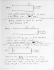
Let me try to explain in detail how an EOL loop works.

You know that a zone operates on a "closed" loop that, when "opened" will alarm. What this means is a magnetic contact that you have in a door or window will act like a simple on or off switch. When the magnet is near or door closed, the contact will short or close, when the magnet is far or door opened, the contact will open.

A short will cause current to flow between the two screw terminals (on the alarm board) of a zone. An open will cause zero current to flow between those two terminals.

Now let’s make up some numbers just for the purpose of this conversation. Say when the contacts are closed or shorted that causes one amp to flow between a set of door terminals (on the alarm board). So when the door opens, zero current will flow between the terminals. Your alarm board knows the difference between zero and one amp and will alarm on any current less than one amp.

Now let’s say someone wants to circumvent your door alarm contact. They make a hole in the side of your house and are able to find the pair of wires that go to your door. If they very carefully strip or nick the two wires and place a "jumper" across them, that will act like a short correct? So, if they do this, then open the door, what happens? Well the door contact opens but guess what, because they have a jumper across the wires going to that contact they "bypassed" it, thus one amp will still flow between the door's two terminals at the alarm panel. The panel will never "see" the door open because of this short, which is between the magnet contacts and the zone's terminals on the alarm board.

So how would one go about to disable this kind of circumvention? Well, wouldn't it be cool if it were a LOT harder to bypass an alarm contact? The way you do this is by placing an EOL resistor near the magnetic contact.

Now, with that EOL resistor in place you no longer have a short circuit, but a circuit with this resistor in the loop. In other words the panel sees the value of the EOL resistor between the terminals at the alarm panel when the magnet contact is closed.

With an EOL resistor in place you will draw a different current value than with a short circuit correct? This is the main reason why EOL resistors work!

Let’s say that you draw .5 amps between the two terminals of your door with this EOL resistor in place and with the door closed. Now, because you set up your alarm panel with this EOL resistor in place (set up its software) it will alarm on any current that is higher or lower then 0.5 amps.

Now if this same person tried to place a jumper across the wires as before what happens? He essentially "shorts" the terminals of that zone, thus causing a lot more current to flow between those terminals (he bypasses the resistor this time and, because you now have a lot lower resistance between the terminals, the current will increase). The alarm will sound as the panel will detect this as a fault.

If he of course just opens the door this will cause an open circuit which causes zero current to flow, which alarms the panel as well (remember the panel was drawing 0.5 amps and anything above or below this value will cause an alarm.

So you can see the value of placing an EOL resistor near the magnetic contacts. If the resistor was placed in the panel instead, when the person shorted the wires with a jumper what would happen? Well, the current between the terminals would remain the SAME because he did not bypass the resistor this time, thus the current does not change and the zone will not alarm.

I hope this makes the EOL concept a little clearer (I'm getting tired of typing so I have to stop :D ). I personally don't use EOL resistors, BUT my Caddx panel lets me have that option (because it changes the current trip level that the zone will alarm now that I don't have any resistor in the loop).

Let me know if you need any further help. We have some professional installers (I just play one on TV) that may also want to give some more helpful comments as well.

Regards,

BSR
 
I will try.

Series.
"In series" means that the electricity will flow through one device, then through the next, then the next, serially. To be more "alarm loop" specific, the current flows out of the panel into one of the wires. Out of that wire into the first switch. Out of the switch into another wire, and on to the next switch. Eventually, the current gets back to the panel, and if all switches are closed, the alarm system senses that the "loop is closed" (all doors and windows on the loop are shut) because the current is flowing through the loop.

If any one switch opens up, it blocks the current from flowing through any of the switches. The loop is open and the panel senses that there is a problem because no current is flowing. The fact that the switches are "in series" insures that any switch can break the flow of current through the loop.

The EOL resistor.
If a nail is driven through the cable (accidentally or on purpose) that happens to bridge the wires coming from and returning to the panel, the loop will be closed by the nail, and it won't matter if the switches are open or closed. The 'short' circuit will make everything look closed, although one or more switches may be open.

But a resistor causes a restriction in the flow of current which appears to the panel as neither ON or OFF, but somewhere in between. If the panel is programmed to only accept this in-between state, then it can treat both the open-loop and the short-circuit as an alarm problem.

But the short-circuit would have to cause the current to bypass the resistor for it to be detected by the panel. The resistor placed at the end of the line will insure that any short WILL bypass the resistor. The resistor placed in the panel will insure that the short WILL NOT bypass the resistor, and it would defeat the purpose.

(Note: By using four wires, you can put the resistor both in the box and at the end of the line. In effect, you are running the end of the line back to the box. However, in this configuration, not all shorts will bypass the resistor, and some shorts might not be detected.)
-------
Well, as usual, BSR beat me to the punch. I must learn to type faster . . .
 
Thanks to both of you for excellent explanations.
I believe I'm finally beginning to understand... :D

Am I right then in thinking a resisitor should be placed in each loop?
Now, exactly how should it be wired? I don't imagine it's wired with one leg to each wire of the contact right? It guess it must be wired with both legs on just one wire of the contact... right? Also, it would have to be located as close to the contact as possible.


Initially, after seeing that video with all the resistors in the panel, then reading here about resistors, I assumed resistors were required. But am I correct in assuming they are not necessarily required, but they are just an added level of security?

The video said something about putting all these resistors in place to avoid errors going off when the panel is first powered up. Is that needed? Does each zone have to be shorted? Or can I just wire whatever zones I need in the panel and level the rest empty?

Thanks for all your help...
 
If the contacts you have are normally open contacts then you need to wire the resistor in series. If they are normally closed, wire them in parallel. Remember if you have several contacts on a zone, you only need a resistor on one of them (usually the last one)

If you look at the 3rd circuit in BSR's drawing, R1 is in series and R2 is in parrallel.

The manual is right in that the panel will go nuts as every zone is pre-configured for EOL supervision. Of course, if you go disable the zones that are not wired in, the panel will calm down.

I think Output 2 may be an exception. I never tried to disable it, but I did put a resitor across it to shut it up. Out2 is special in that it is for a siren and has supervision.
 
Back
Top