I am trying to install a pair of linked Insteon 3 way switches and I am having a really difficult time getting this done. I currently have 2 light switches that control about 8 recessed lights.
The problem I seem to have is there appears to be an additional wire that I don't know the purpose of it is.
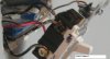
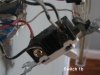
As you can see in the pictures Light switch 1has two wires that connect to the black terminal screw. One is a punch in and the other is screw in. The punch in always has 120v going to it. The other connection to the screw terminal and the black wire connected on the bottom has voltage depending on wether the light is on. I also have the red cable which I believe is going to the lights and of course the ground.
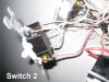
For switch two I have 2 black wire punch ins and again the red wire with I assume goes to the lights.
I have a set of white neutral wires in the back of the box.
I followed the instructions for creating the virtual 3way switch but I can't seem to get either of the switches to turn the lights on and off.
The problem I seem to have is there appears to be an additional wire that I don't know the purpose of it is.
As you can see in the pictures Light switch 1has two wires that connect to the black terminal screw. One is a punch in and the other is screw in. The punch in always has 120v going to it. The other connection to the screw terminal and the black wire connected on the bottom has voltage depending on wether the light is on. I also have the red cable which I believe is going to the lights and of course the ground.
For switch two I have 2 black wire punch ins and again the red wire with I assume goes to the lights.
I have a set of white neutral wires in the back of the box.
I followed the instructions for creating the virtual 3way switch but I can't seem to get either of the switches to turn the lights on and off.