HVAC Selector Wiring

bfisher

Active Member
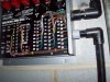
I have been upgrading my HVAC system (installing RCS TR16s) to control the 3 zones. The original zone controller (MasterTrol Mark XXXI) has a seperate main Selector Switch (and slider) to determine Heat/Cool/Fan/Auto.

Since I have an automation system, I would like to tie this switch into the automation system so when we change the switch from Heat to Fan or Cool, the thermostats know it and I don't need to go to each stat individually and change them.

I have been trying to determine the wiring for this knob, and have been unsuccessful and am wondering if anyone here has the patience or experience to figure it out. Or if someone can tell me what wires to test with a voltmeter I'd be happy to... my fear is I "blow" something by touching two wrong ones together.

All I really need to know is when the knob is switched over to Heat. Cool/Fan or Off are the alternate, and it really doesn't change the thermostats at all (all three of these will have the same TStat settings).

Link to the Switch

If you click on the link above, there is a PDF that has a very basic wiring diagram but I haven't been able to figure it out. I think 11 and 17 both indicate heat... but how do I wire this back to my automation system? All I want to know is when the knob is on Heat. If it is - then I'm in Heat mode. If it is not - it is either off, cool or fan - either way it doesn't change the thermostats.

Sorry if these are basic questions... HVAC makes me nervous - I don't want an expensive repair! :(

Thanks!
 
How come you don't just control the Heat/Cool/Auto with the mode button on the TR16 and the Fan with the Fan button? These functions can be controlled directly with an automation system so why use a separate switch?
 
I would be happy to get rid of the switch... The problem is that the original HVAC Controller (3 zone controller) requires it. I don't think I can eliminate it without some serious wiring work to get my automation system to "look like" the switch. So I figured it would be easier to keep the switch, and have it change the tstats mode via the automation system (when automation sees switch change to Heat - it changes the TStats to Heat, etc)
 
Sorry, I guess I don't understand what you are doing. I thought you were replacing an existing zoned thermostat system with either an RCS zoned system or 3 stand alone thermostats.

I don't know what you mean when you talk about wiring your automation system to "look like the switch". I pictured a scenario where you completely replace the MasterTrol stuff with RCS and get that working ignoring HomeVision for the moment. Then once the RCS stuff is up and running you can use logic in HomeVision to note when you change the mode at any thermostat and change the other thermostats to match.

I probably have the wrong idea about what you need to do.
 
Sorry - I tried to simplify my description of what I was doing and that probably confused you.

I am keeping the original 3 zone controller (MasterTrol Mark XXXI) because it works fine. I looked at replacing it with the RCS 4 Zone controller, but my dampers are incompatible and I didn't want to replace them too.

So what I'm doing is replacing the old thermostats with 3 new RCS TR-16s. These thermostats will communicate to the HomeVision system for changing setpoints, etc. and will behave to the old controller as simple thermostats.

The old controller has an existing switch (that I don't mind keeping if needed) that switches from Heat to Cool to Fan. I just want to know what setting that switch is set for - then my HomeVision can update the TStats which mode to be in. If I don't know the switch status, I need to update HV so it can update the switches (not a big deal, but always trying to eliminate a step).

Thanks
 
It looks like the voltage at terminal 12 will be present at terminal 11, 14 or 15 depending on the switch setting with no output for OFF. 17,18 and 19 look to be in line with the thermostat so voltage there will depend on the thermostat setting. Looks like voltmeter time!
 
thanks Mike. Any recommendations how to check the voltage? Any risks (not as much to me but the HVAC system) I need to be aware of?

If I understand you correctly, I check the voltage between 11 and 12; and 14 and 12. I should expect to read a voltage between 11/12 if knob on heat, and 14/12 if on cool or fan.

I apologize for the (hopefully) easy questions, it's been some years since my EE classes (which I don't use anymore). Thanks again.
 
Yep, it looks like it's intended to route the 24VAC control voltages around. But I've got the impression that there might not be usable voltages present unless one of the thermostats is actually calling for heat/cool (and could easily be wrong).

Voltmeter time, definitely. In addition to that, is there anything wired to 17/18/19 (I'll bet there is, but I can hope...)?

Is your system a heat pump? Separate A/C and heat? Gas? Nuclear? Just trying to figure out how it all ties together.

Whoops, just saw your reply. Here's how I'd start. You just need a basic voltmeter. Rotary switch off. Fan switch in auto. Measure and record the following voltages:

12 - 11
12 - 14
12 - 15
11 - 15
14 - 15
18 - 17
18 - 19

That'll get us started, anyway...

Jerry
 
12 is your source. Whatever is at 12 seems to get routed from 12 to 11 14 or 15 depending on the setting. The voltage is probably a 24vac contol voltage. Your first test proabably should be to find the other side of the 24vac (return). Not sure if the return is present in the switch so you may have to go back to the transformer if it is external. Once you get a good reading between your source (12) and your return (the point you need to find) you can then use the return point as your reference for all other readings. Reading between 11 and your reference point should give you a voltage only when the switch is in one position while a reading between 14 and your reference point will show a voltage only when the switch is in a different position.

Once you get that figured out you need to wire up 3 relays to activate when there is voltage at each of 11, 14, or 15. The relays should be designed for 24vac and should draw substantially less current than the thermostat circuit so as not to impact normal operation. Maybe a small elk relay set to 24V with a bridge rectifier on the coil to convert the AC to DC.

Optoisolated inputs would be better than relays as there is less risk that they might affect the original circuit. Make sure the input is rated for at least 32VAC for use on a 24V circuit.

Another detection method might be the doorbell detector module from elk. Three of these could be wired in series with the connections to 11, 14, and 15 and then you don't have to locate a voltage reference point. Just think of the selector switch as doorbell buttons!
 
Thanks for the help guys - here are the answers:


I've got the impression that there might not be usable voltages present unless one of the thermostats is actually calling for heat/cool (and could easily be wrong).
That makes sense and I think you are right.

In addition to that, is there anything wired to 17/18/19 (I'll bet there is, but I can hope...)?
yes - 17, 18 and 19 are wired into the 3 zone controller's 17, 18 and 19.

Is your system a heat pump? Separate A/C and heat? Gas? Nuclear? Just trying to figure out how it all ties together.
Electric AC and gas heat.

You just need a basic voltmeter. Rotary switch off. Fan switch in auto. Measure and record the following voltages:
All of the requested voltages were bouncing around +/- 100 mV except 14-15 - that one was fixed on 0.0 mV.

Your first test proabably should be to find the other side of the 24vac (return). Not sure if the return is present in the switch so you may have to go back to the transformer if it is external.
I'm not sure how to find this return. Looking at the HVAC Controller wiring diagram (on the inside of the cover of the unit), I see where the transformer is wired in (has 2 screw terminals labeled 1 and 2 (labeled 24V 40VA Transformer).

There is also another set of screw terminals (on the left) that goes to various devices (Compressor Relay, Reversing Valve Relay, Fan Relay, 24 V Transformer (labeled common), Emergency Heat Relay, and 2nd Stage heat Relay). The one labeled 24V Tranformer (Common) has 2 wires connected to it - one goes to #2 (paragraph above) and the other goes into a wire bundle and I assume into the furnace controls.

My guess is that #2 is the return you mention. Sound right?

Thanks again for your help!
Bruce

Edit: I've taken a picture of the MarkXXXI Controller if it helps. On the Left is the Common I refer to above (labeled R with the Red Wire). It goes to #2 bottom middle which according to the diagram is the 24V Transformer.
 

Attachments

  • 000_0573.jpg
    000_0573.jpg
    102 KB · Views: 47
Switch the voltmeter to AC and try again :)

Oooh. That picture helps a lot. I'm betting the second column of terminals (10-19) is labled "System Selector Switch" under the wires. That goes directly to your selector switch.

This just got a lot easier. Terminal 1 should be your return line. Terminal 2 connects to "Common" as it is the common line to feed all of the relays (simplifying).

So now all you have to do is figure out which terminal has voltage (with respect to terminal 1) when you are in the mode you want to detect. Make certain that you do it with and without the system running so that you know that you have the selection line and not the call line.

Once you've got that isolated, then we can figure out how to connect it into your ha system (I'm thinking small relay might be easiest here).

Jerry
 
I think 2 and 12 are connected together so they are the same thing. you can confirm this by measuring the voltage between 2 and 12 (I expect it will be zero volts). You want to connext one side of the meter to 12 and move the otherside of the meter around until you find a point that reads around 24VAC.
 
Switch the voltmeter to AC and try again
How embarrassing :(

OK - I tested various combinations and have the following results (see attached chart (heat off=knob on heat, not running; heat on = knob on heat, heat running, etc). Looks to me that 18-19 is my best bet... Shows me Off or Heat. I don't much care if it's OFF since nothing will happen regardless of the TStat readings.

So now that I have this, I need to figure out how to best get it into my HomeVision Pro. My HV Inputs don't accept VAC, so I need an external relay board.

You mentioned a doorbell relay - I assume you are refering to the Elk 930? Is this the best/easiest way? I hate to spend $45 to monitor a switch that gets changed 2-3 times a year. I was hoping for the <$10 range :)

Thanks!
 

Attachments

  • HVAC_Voltages.jpg
    HVAC_Voltages.jpg
    32 KB · Views: 27
How embarrassing
Don't worry about it - we all do it from time to time. Just how do you think I knew what you had done? :)

That chart is pretty thorough - good job! But as much as I hate to say it, we need some more.

You see, your picture makes thing a lot clearer. If terminals 11-19 on the controller match 11-19 on the switch as I expect (a quick rundown of the colors at both ends should do it), then I'd concentrate on making all measurements and changes at the controller box.

Doing it here has the advantage of having our transformer return line in the same place. Just to note, I made one "whoops" in my last post - I meant to say "measure with respect to terminal 1" (it's corrected now).

With what I'm seeing in the chart, I'd like to see what you have from terminal 1 to each of terminals 11, 12, 14, 15, 17, 18, and 19. I think you'll find that 18 is always 24VAC (roughly). I expect 17 to have 24V in Heat, and 19 to have 24V in Cool and Fan. I'm less certain about the rest will show - and it wouldn't shock me to be totally wrong anyway. But that's why we're going through this fun exercise - I'm a wee bit paranoid when it comes to suggesting changes to somebody else's system!

Just so I can dig up some more info, which model controller is this? I can _almost_ read it - Model MABS *something*. Maybe Mark XXXI will be sufficient - will dig.

What do you have on your ha system for reading inputs? Ideally we need something that will detect if a simple switch is open or closed. The elk module is really a pre-built version of what we would try to create. It also would handle three separate inputs - maybe you can come up with some uses for the other two? Or try and monitor all modes? Otherwise we'll just make something using a simple relay or a hand wired opto-coupler.

Jerry
 
Thanks for the response. I will work on getting those voltages tomorrow and post an update.

It is a Trol-A-Temp Mastertrol Mark XXXI. It has since been sold to Honeywell (best I can tell). I've done several searches and been unsuccessful for any sort of wiring diagrams (other than a very basic one on the lid of the controller). I can take a picture of it tomorrow if that would help.

As for my HA inputs - the HVPro has 8 inputs supporting +/- 30VDC, and 8 inputs of 0-5VDC (or they can be 8 outputs 0-5VDC) and 8 SPDT relay outputs (10A at 125VAC).

I appreciate the help!
Bruce
 
Back
Top