New ELK M1 planning - New home

RAL said:
With the two M1XINs, you're just a bit over the limit, but that's a worst case number when everything is drawing power at once.  That wouldn't be the normal state. but could happen in an alarm condition if every component was drawing its maximum power.  You might be able to squeak by without an aux power supply.
 
Good design practice (and my preference) is not to push things right to the limit, but to leave some head room.  I usually try and keep the loads to around 80 to 90% of the maximum allowed. It requires more work  and a bit more cost up front, but avoids headaches when things don't work as they should.
 
A multi-output power distribution board isn't required, but makes things a bit neater and easier to wire up.  One advantage is that each output has it's own fuse, so if a short develops somewhere down the line, it will take down part of your system, but not all of it. 
 
4, 8 , or 16 outputs is up to you.  On my system, I divided things up by the type of load.  One output for motion detectors, another for glass break sensors, etc. 8 outputs was sufficient for my system.
 
If you find a real bargain on a 4-output Altronix power supply, you can always swap the distribution board for a larger one later.  The boards are often on eBay for $10-$20.
 
There's a choice of fuses or PTCs on the distribution boards.  Fuses are usually the better choice for a residential installation.
 
RAL,
I agree and thanks for the advice. The power supplies usually have efficiency rating so 80% is a good place to be in. I went ahead and ordered an Altronix AL400UXPD16 for $35 off of ebay. The item is new without batteries and the panel/box has some damage. I can live with that. I will order 2x 12Ah batteries to use with it. The batteries are going for $30 a piece in eBay.. decent price?!
 
Now I need to get couple of zone expanders and M1XEP. This will set me back another $250-$300 I guess.
 
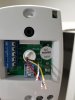
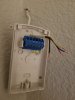
I have another problem, .t was self made though. When I wired my new house, I ran 3 wires to most of the rooms (motion, glass breaker and window sensors. Two 22/4 and one 22/2 wires. I have identified all of the window sensors as they are 22/2 but I am having trouble tracing the 22/4 wires now as the house has already been foam insulated.  Any tips on how to identify the wires before/after connecting the devices? 
 
I'd like to label them like BR1WIN, BR1MOT, BR01GB etc. It's a single story home so I don't bother using Floor # in the labels.
 
Thanks for all the help. 
 
I saw that AL400 on eBay.  At $35, it's a good bargain.  You can probably straighten the bent part of enclosure back to something near normal without too much effort.
 
For batteries, I like Power Sonic batteries.  $30 with free shipping is a reasonable price.  The PS-12120 batteries are available with 3 different connectors:  F1, F2, and NB.   Altronix uses F2 connectors, if I remember correctly.
 
One way to figure out which cable is which is to short two of the wires in a single cable (say black wire to red wire) at a time, and then test all the wires back at the panel end with a multimeter on the Ohms scale until you find the cable that's shorted.  Slow, but it works.
 
A faster way is to get a tone generator and probe set.  There are some inexpensive ones on eBay and Amazon that will do ok if you have both ends of the wire available.  Fluke makes a great one, the Pro3000.  The Fluke can easily trace wires hidden in the wall when you aren't sure of exactly where they are.  The less expensive ones can also do that, with varying degrees of success.  It's all a matter of how well they can pick up a signal.
 
Watch out on eBay.  Some auctions are for the tone generator only, others just for the probe.  You need the complete set.
 
With the tone generator/probe set, you use them with no devices connected to the cable.  You connect the generator to one end of the cable, say in one of your rooms. and then use the probe to sweep over the bundle of cables aback at then panel.  When you are close to the right cable, the tone increases in volume.  If a cable is hidden in the wall, you can usually track down where the end of the cable is by connecting the generator back at the panel, and then sweep the probe over the wall or a room, around windows or doors, wherever you think the cable might be. 
 
RAL,
I don't know what I would have done with all your help. Thank you so much. I ordered the batteries, relays etc. The only piece I am missing right now is the M1XEP Ethernet interface. 
I will get a tone generator probe set...most probably the pro3000.
Now the structured wiring panel... what size panel do I really need to house all these boards? I don't think the one I got with M1 gold is big enough. Do I need to stick to Elk panel or any would work?
 
The SWB14 enclosure that comes with the M1 kits will be a tight fit if you're adding 2 M1XINs.  I used a SWB28, which gives you twice as much room.  Some folks use other structured wiring enclosures, such as those from Leviton or Legrand.  I liked the Elk enclosure since it has pre-drilled mounting holes for the M1 and for SWG mounting blocks that allow you to mount the boards on-edge.  
 
You could also get a second SWB14 and split things between the two 14" enclosures.   There's lots of ways you can do things.
 
I have the Bosch Blueline Gen2 PIRs and interlogix 5812-RND glass breaks attached to my M1G.

Happy with the PIRs. The kids set off the GBs occasionally, I've set them off putting silverware away. I ended up changing the GB zones so that they only alarm when the system is armed, otherwise they simply chime.

...v
 
RAL said:
Elk has some good photos of M1 installations in their Hall of Fame. The pictures will give you some ideas about how you might want to lay out your system.
 
Here's one with a M1, XEP and one M1XIN in a SWB14.   You could squeeze another M1XIN in there, but if you had a second battery, it would be pretty packed.   And here's another.
 
 
I'm back with some more questions as I am getting ready to install the devices..
1. I ran cat5e cables in daisy-chain in 3 locations for 3 keypads.. Do I need a M1DBH to connect all 3 keypads? 
2. I misunderstood running a speaker wire to locations near the keypad. Instead I ran a speaker wire from the keypad to ceiling for speakers. Do I need to home run speaker wires in all 3 locations?
 
Thanks!
 
1.  If you daisy chained the wiring to the 3 keypads, then you don't need a M1DBH to connect them.  You would use the M1DBH if you had home runs to each keypad using Cat5/6 cable.
 
Do you have any other data bus devices like input expanders that you'll be connecting?
 
2. Yes, you'll want a home run speaker cable from the M1 to each keypad location, or at least somewhere nearby that would allow to hear the M1 announcements when you are using a keypad.
 
The M1 wants a 4 to 8 ohm load for the speakers connected to Output1.   You'll need to connect whatever speakers you use in a series/parallel arrangement so that in total, the combined impedance is in the 4-8 ohm range.   This is easiest to do if you home run all the speaker wires.  Note that the SP12F is 32 ohms but the Elk-73 is 8 ohms.
 
You could also use the M1 to drive a small multichannel amplifier board to drive the speakers individually if you want to set different volume levels for each speaker.
 
RAL,
Thank you. No, I do not have any expanders I will be connecting. How do I wire the keypads here? I only use 4 wires out of 8 in the cat5e cable? Do I just connect two leads in each terminal on the keypad?
Good thing is I put a conduit on the wall where alarm panel will be installed so I should be able to homerun speaker wires. I will look at the amplifier option once I get the current setup installed and tested. 
 
CO2/Smoke detector: I thought I ran wires for the 4wire cosmo smoke/co2 detectors but I couldn't find those. These wires need to be home run as well? 


RAL said:
1.  If you daisy chained the wiring to the 3 keypads, then you don't need a M1DBH to connect them.  You would use the M1DBH if you had home runs to each keypad using Cat5/6 cable.
 
Do you have any other data bus devices like input expanders that you'll be connecting?
 
2. Yes, you'll want a home run speaker cable from the M1 to each keypad location, or at least somewhere nearby that would allow to hear the M1 announcements when you are using a keypad.
 
The M1 wants a 4 to 8 ohm load for the speakers connected to Output1.   You'll need to connect whatever speakers you use in a series/parallel arrangement so that in total, the combined impedance is in the 4-8 ohm range.   This is easiest to do if you home run all the speaker wires.  Note that the SP12F is 32 ohms but the Elk-73 is 8 ohms.
 
You could also use the M1 to drive a small multichannel amplifier board to drive the speakers individually if you want to set different volume levels for each speaker.
 
I just went back and re-read the earlier part of this thread.  You had said you will have some M1XIN input expanders.   Are you still planning on using them?  
 
The M1 can have 2 branches on the data bus, with multiple devices on each branch, all wired as a daisy chain on each branch.  So if you are planning on one branch for keypads and the the other for the M1XINs, that's fine.  Or you could put everything on a single branch, as long as wiring the daisy chain that way makes sense.  E.g. say you wire the M1 to the first M1XIN, then daisy chain to a second M1XIN and then on to the keypads from there.  That would be fine.
 
I just want to make sure I'm still in sync with your plans when giving you advice.
 
For the keypad daisy chain, I would use 6 out of the 8 wires in the Cat5 cable and double up on the power wires for NEG and +12V.  The data bus devices are sensitive to voltage drop and since you will be powering 3 of them through the daisy chained cable, doubling up will reduce the voltage drop.
 
The Data A and B signals are low current, so a single wire in each cable for each signal will be fine.
 
At each keypad, just twist the wire from the incoming cable, the keypad pigtail, and the outgoing cable to the next keypad together and cap them with a small wire nut or use a Dolphin type crimp connector.  For the power wires, you'll have 5 wires in each connection.
 
The wires for smoke/CO detectors should be daisy chained.  If you were to home run them using 4-wire cable, you could still form a daisy chain back at the panel if you use 2-wire smoke detectors.   But for 4-wire detectors, you'd need 2 home runs of 4-wire cable from each location to build a daisy chain back at the panel.
 
In general, it's easier to use 2-wire smokes rather than 4-wire smokes, as you don't need EOL relays to supervise the power. 
 
RAL said:
I just went back and re-read the earlier part of this thread.  You had said you will have some M1XIN input expanders.   Are you still planning on using them?  
 
The M1 can have 2 branches on the data bus, with multiple devices on each branch, all wired as a daisy chain on each branch.  So if you are planning on one branch for keypads and the the other for the M1XINs, that's fine.  Or you could put everything on a single branch, as long as wiring the daisy chain that way makes sense.  E.g. say you wire the M1 to the first M1XIN, then daisy chain to a second M1XIN and then on to the keypads from there.  That would be fine.
 
I just want to make sure I'm still in sync with your plans when giving you advice.
 
For the keypad daisy chain, I would use 6 out of the 8 wires in the Cat5 cable and double up on the power wires for NEG and +12V.  The data bus devices are sensitive to voltage drop and since you will be powering 3 of them through the daisy chained cable, doubling up will reduce the voltage drop.
 
The Data A and B signals are low current, so a single wire in each cable for each signal will be fine.
 
At each keypad, just twist the wire from the incoming cable, the keypad pigtail, and the outgoing cable to the next keypad together and cap them with a small wire nut or use a Dolphin type crimp connector.  For the power wires, you'll have 5 wires in each connection.
 
The wires for smoke/CO detectors should be daisy chained.  If you were to home run them using 4-wire cable, you could still form a daisy chain back at the panel if you use 2-wire smoke detectors.   But for 4-wire detectors, you'd need 2 home runs of 4-wire cable from each location to build a daisy chain back at the panel.
 
In general, it's easier to use 2-wire smokes rather than 4-wire smokes, as you don't need EOL relays to supervise the power. 
RAL,
 
Yes, you are correct. I do have 3 input expanders and planning on using at least 2 of them in addition to the main board terminals. 
"E.g. say you wire the M1 to the first M1XIN, then daisy chain to a second M1XIN and then on to the keypads from there.  That would be fine." So the expanders and keypads are on data bus and they should be daisy chained?
I am only trying to get the devices mounted on the wall for now. Will focus on connecting them to the board once I finish mounting all.
 
1. 3 fire detectors connected in daisy chain using fire resistant cables
2. Bosch Blue Gen2 motion sensors home run using 22/4 
3. FG-1625 - homerun - 22/4
4. Tane contacts for doors and windows - home run - 22/2 (some contacts in daisy chain that are in the same room multiple windows with EOL)
 
Thanks as always for the help
 
Can someone tell me how the 4 leads on 22/4 to be connected to the motion and glass break sensors?
Thanks!
 
Please see pictures.
 

Attachments

  • 20190213_205104.jpg
    20190213_205104.jpg
    49.9 KB · Views: 9
  • 20190213_220122.jpg
    20190213_220122.jpg
    40.5 KB · Views: 9
Nixer said:
Can someone tell me how the 4 leads on 22/4 to be connected to the motion and glass break sensors?
Thanks!
 
Please see pictures.
 
A glass break sensor is connected to a zone on the panel with two wires like any other sensor but it also requires two wires to supply a 12 volt power supply. The instructions that came with the sensor whould diagram where each wire goes and this video may help:
 
https://www.youtube.com/watch?v=1NEtzHznqss
 
Mike.
 
It's up to you what color wires you choose to use for which purpose.  Make a rule you can remember and stick with it. 
 
I like to use Red for +12V, Black for NEG/GND, and then use the remaining two wires for the zone input.  e.g. Green for NEG/GND, and Yellow for the +Zone input.
 
Looks like you have a blue wire rather than green, so just use blue where I say green.
 
 
On the terminal strip, connect
 
+12v (Red) wire to   "+" or V+
NEG/GND (Black) wire to   "-" or V-
Zone NEG/GND (Green) wire  to NC
 
If you are not using EOL resistors, connect the Zone+ (Yellow) to the other NC or C terminal.
 
If you are using EOL resistors, connect one end of the resistor to the NC or C terminal, and connect the other end to the Zone+ (Yellow) wire.  Use a crimp connector on this.  Or you can solder it and insulate it with heat shrink tubing. On the glass break detector, you can use the EOL terminal to make the connection between the resistor and Yellow wire.   This is shown in the instruction sheet.
 
RAL said:
It's up to you what color wires you choose to use for which purpose.  Make a rule you can remember and stick with it. 
 
I like to use Red for +12V, Black for NEG/GND, and then use the remaining two wires for the zone input.  e.g. Green for NEG/GND, and Yellow for the +Zone input.
 
Looks like you have a blue wire rather than green, so just use blue where I say green.
 
 
On the terminal strip, connect
 
+12v (Red) wire to   "+" or V+
NEG/GND (Black) wire to   "-" or V-
Zone NEG/GND (Green) wire  to NC
 
If you are not using EOL resistors, connect the Zone+ (Yellow) to the other NC or C terminal.
 
If you are using EOL resistors, connect one end of the resistor to the NC or C terminal, and connect the other end to the Zone+ (Yellow) wire.  Use a crimp connector on this.  Or you can solder it and insulate it with heat shrink tubing. On the glass break detector, you can use the EOL terminal to make the connection between the resistor and Yellow wire.   This is shown in the instruction sheet.
 
Great, thanks guys... now do I need an EOL connector for each of the home run glass breakers and motion detectors?
 
2. Bosch Blue Gen2 motion sensors home run using 22/4 
3. FG-1625 - homerun - 22/4
 
Back
Top