Open collector outputs and M1G zones

Ira

Active Member
I want to control a group of M1G input zones (on an M1XIN) with a device that has what it calls "open collector outputs" (aka, O.C.O.). The device manual says the following about connecting external devices to the O.C.O.'s...

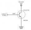
Open Collector outputs are ideal for adding external relays, small lights, LEDs, and other small loads under 150ma at 12VDC. OC outputs work by connecting an external device to ground. For instance, to connect an external relay to an open collector output, you will connect one of the two power leads directly to the OC output. The other relay power lead should be connected to a power supply. The ground of the power supply should be shared with the Ground leads on the OC output.

The device/board has a terminal block with sixteen pairs of screw terminals, and a 12Vdc +/- terminal block.

Can I use the device by itself to open/close the M1G zones, or do I need to use a relay (for each zone) between the device and the zones in order to provide dry contacts for the M1G zones? If I don't need to use relays, how does this thing get wired up assuming I want the zone to be a normally open zone? The part I don't understand is how to implement the "ground switching" requirement of the O.C.O. device.

Thanks,
Ira
 
I'm not sure I understand exactly.

Here is what I think you are saying:
The OCO is a device that has multiple outputs on it that supply 12vdc, up to 150ma each? Something switches those outputs on/off?

You want to switch an output on/off on the OCO and have an Elk zone report the status?

If what I say is correct, you would need to connect the OCO outputs to a relay coil and connect the NO/common or NC/common relay terminals to the two leads from an Elk zone.
 
Here is a link to the device.

It (the "OCLP") is connected via jumper cable to another device that sends the OCLP signals. As you can see in the picture, there are two terminal block banks, with each bank containing eight pairs of OCO terminals. So lets say that when the OCLP "turns on" it's bank 1 channel 0 OCO (signified by the two terminal block screws in the upper left hand corner of the picture), I want to close a N/O relay. According to the OCLP manual, I need to run the positive wire from an external 12Vdc PS (different PS than the one powering the OCLP) to one side of the external relay's coil. I need to run the negative/ground wire from that PS to one of the two bank 1 channel 0 terminals, then a wire from the other bank 1 channel 0 terminal to the other side of the external relay's coil. I also need to connect the external PS's ground to the OCLP's PS ground (i.e., the grounds must be "shared"). So according to the manual (but I haven't tested this yet), when the OCLP turns on the bank 1 channel 0 OCO, the external relay contacts will close (until the OCLP turns off the bank 1 channel 0 OCO). The important thing is that the OCO is switching the external PS's ground instead of its positive voltage output. Using the OCO to switch the positive wire will supposedly damage the OCLP.

But, what I really want to do is use the 16 OCO's to trigger 16 ELK M1G M1XIN zones (one zone per OCO channel), without using 16 external relays in the middle, if it can be done. I don't think it's as simple as wiring one of the channel's OCO terminals to the zone's positive terminal and the channel's other OCO terminal to the zone's negative terminal.

Ira
 
Set the zone to End Of Line resistors, place the end of line resistor on the zone input, and put the Open Collector output device on the zone side of the end of line resistor, not on the negative side. When the Open Collector device shorts to negative, it will violate the zone input.
 
Spanky,

Not sure I understand. Let's assume I want to use zone 1. So on the M1XIN, there are terminals marked Z1 and NEG. On the OCO device, there are two terminals associated with the channel/zone, and neither one is marked, but let's call them OCO1a and OCO1b. Is the following correct?

Z1 connected to OCO1a
OCO1b connected to one side of EOL resistor
other side of EOL resistor connected to NEG

Thanks,
Ira
 
Essentially he is saying to connect the resistor directly across the zone input and its corresponding ground terminal so the zone is satisfied with 2.2K. Think of the OC output as a normally open contact as shown in the elk manual. Wire the OC output wires to the same two terminals as described above. When the OC turn "on" it will be like shorting a wire across the zone input and show a short to the panel violating the zone.

Are these OC Boards being powered from the elk supply?
 
I tried to download the owners manual on that thing but it gave me a manual for some other board.

It appears to me that the OC functions like a relay with very low specs. It is prbably a transister gate that closes and opens from a very low power logic level signal from the chip on the board. I have a relay board that works the same way but it puts the transistor and the actual relay together on one board. The logic level turns the transistor on which closes a gate sending power to the relay.

Anyway, I see two screwdowns at each location. I assume the two terminals close/open when active/inactive. So you could think of it just like gatchel said as a typical contact closure such you would have on a window or door.

It appears to me that the board has its own separate 12v supply.

You probably downloaded the correct manual. It's for a family of products. The info pertaining to this is at the bottom of page 27 (out of 44) when I view it with Adobe Reader. The top of the page says "Connecting 5Amp/10Amp SPDT Relays". Then the bottom half of the page says ""Connecting O.C. Outputs to External Devices". There's an actual diagram for connecting a relay to the OCO's. The diagram shows it the way you describe, i.e., each pair of OCO terminals look like a set of relay contacts, but the manufacturer is adamant about 1) switching the ground thru the OCO, and 2) having shared grounds between the OCO board and the external relay/device. I can understand how to hook up a relay. What I'm having a hard time visualizing is how to connect the OCO outputs directly to an Elk M1G zone. I've been warned by the manufacture that hooking it up wrong may damage the board. At close to $100 for the board (not to mention the cost of the M1G if I damage it), I'm concerned about that.

What I really need is for someone to give me beginner wiring instructions similar to what I suggested in my last post.

Thanks,
Ira
 
Essentially he is saying to connect the resistor directly across the zone input and its corresponding ground terminal so the zone is satisfied with 2.2K. Think of the OC output as a normally open contact as shown in the elk manual. Wire the OC output wires to the same two terminals as described above. When the OC turn "on" it will be like shorting a wire across the zone input and show a short to the panel violating the zone.

Are these OC Boards being powered from the elk supply?

I didn't read Spanky's comments quite that way. At first, I saw the EOL resistor comment the same way you did, i.e., put one end at Z1 and the other at NEG for the zone. Then he said...

...put the Open Collector output device on the zone side of the end of line resistor, not on the negative side.

That's the part that threw me, and why I came up with the connections I previously posted. If there was only one terminal on the OCO, I would have thought he meant running a wire from that terminal to the Z1 terminal. But since there are two OCO terminals, I'm confused.

Thanks,
Ira
 
I wonder if the issue is that all of the commons on the OCO board are shared and if there aren't some connections to the processor or other components.

The basic deal is that I think the OCO wants all electricity entering one of the contacts to have an obstructed path to ground after exiting the other side (no load, no resistors, just wire)

Elk has a power supply presumably going to an internal load (a resistor for limiting current), then to the positive lead on the elk and then back to the common which goes directly to ground (please confirm that common on the Elk is resitance free to ground but I think it is). If you wanted to put an eol resistor, you would want to put it between the positive lead on the Elk and the OCO, so that once the electricity enters the OCO, it can exit the other contact and have a non-loaded path to ground.

Any load on the negative side would "push back" voltage possibly shunting through unintended paths in the OCO and damage it.
 
What you are discussing here is a very common use of a transistor as a switch.

"Open collector" refers to the transistor terminal, the COLLECTOR, that connects to the load to be switched. It is "open" because it is not connected to anything -- it is deliberately left open for your use. The transistor EMITTER terminal in this configuration is connected to ground, and the transistor BASE terminal is what controls the on/off state of the transistor.

When the transistor is ON (conducting), there is a low-impedance path from the COLLECTOR to the EMITTER. In other words, it functions just like a closed switch. When the transistor is CUT OFF, there is high impedance between the COLLECTOR and the EMITTER, same as an open circuit.

To use it, you simply connect your device to be controlled to the OPEN COLLECTOR terminal, with positive power connected to the other side of your device. Your power supply common or negative or ground terminal connects to the transistor EMITTER.

Yes you need to pay attention to polarity and you need to understand whether all 16 transistor emitters are connected in common.

(BTW, in the term "Vcc" as a supply voltage, the "cc" comes from COLLECTOR.)

[Edit: Corrected the drawing to show an NPN transistor (!) - thanks Photon]
 

Attachments

  • Open Collector.jpg
    Open Collector.jpg
    13.8 KB · Views: 3
I never like this arrangement because you are linking the 2 systems together. If they are being powered from the same power supply or a power supply that is common to the M1 supply you will probably be OK. I always feel it is better to "talk" between "systems" with relays instead of open collector or open drain (MOSFET) connections. It gives a level of isolation between the two systems. Unfortunately, it usually costs more. Just my $0.02
 
Thanks Lagerhead, I suspected transistors.

I am not seeing any polarity markings on the picture of the OC device. The owners manual bottom of page 27 has a picture of the unit that is different, however, and it does have polarity markings.

The page 27 answers one of the other questions, and that is: "don't forget this circuit will share the ground of your external power supply with the ground and rs232 ground of the controller". So, if you put a load between the OC and the ground, you will present the OC with voltage that will force current up into the grounds of the unit. And, if you don't have any load between that power supply and the OC, then the power supply will be hooked directly to ground and you will short it out through the OC which I am sure will fry it.

Provided the only thing your are connecting to the OC are Elk zones, there should be no risk of damaging the Elk (elk zones positive terminal already has an internal 2200 ohm load making a short to ground OK not really a short), but I do see a potential risk to the OC if you hook it up wrong, however it would be small considering Elk zones only put out 6ma.

I can confirm by actual measurement that the common's on the Elk mainboard are common to ground on the Elk's power supply.
 
To me, it seems lagerhead's drawing suggests only one terminal (per channel) on the OCO device. For example, if I'm using it to switch a relay coil, one side of the coil would be connected to a PS positive. The other side of the relay coil would be connected to the OCO terminal. When the OCO signal tells it to close, it completes the relay coil's circuit by sending the wire attached to the terminal to ground. Since all the grounds are shared/connected, the relay coil is energized.

But this particular OCO device has two terminals, and the drawing in the manual shows the relay coil's negative going "across" those terminals. It's like the OCO is acting like the contact side of a relay to complete the circuit when the contacts are closed instead of connecting the ground wire to a common ground.

So anyone know of any off-the-shelf board with relays or opto-isolators that I can use between this thing and the Elk zone?
 
Back
Top