Pull Up resistor wiring

siafu

Active Member
Greetings all,
 
I'm having a hard time wiring a pull up resistor as per the Webcontrol manual where it is mentioned to wire a 2.2k pull up resistor to fix the issue where you get multiple emails when a button is pushed.
 
I have two button push type inputs on my board, and when the inputs get a signal they send multiple emails, normaly two emails per push, but sometime more.
 
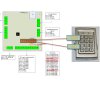
On IP1 i have two wireles coming from a push button that one of the wires is hooked to IP1 and the other to GRD on the input module on the cai board.
 
The other is as well a 2 wire coming from a keypad and one wire is going to IP2 and the other to the 5v on the input module of the cai board.
 
I'm getting emails but too many and as this is mentioned in the manual that there is a solution I would like to fix this.
 
IF someone could do a small drawing that would be greatly appreciate it, as I can't figure it out by the description.
 
Thank you very much.


Well normally a pull-up resistor would connect from the 5V line to the input. The push button (normally open) would connect from the input to ground.
 
That may solve your problem but normally when connecting a mechanical switch like this to an input you need to "debounce" the input. This is because inside the mechanical switch (when you push it) the contacts literally bounce for a small amount for time, making and breaking the circuit multiple times, before they settle down and make a permanent connection (until you release the switch). Debouncing can be done with a hardware circuit (which your input may already have) or it may be done in software (which you program may be doing).
 
I don't know your hardware/software at all but IF nothing is debouncing the input you will often get multiple activations of whatever it is the push button switch is supposed to do.
 
like this?
 
7-12-2013 11-34-49 AM.jpg


and here is the PLC code I'm using.
 
START    
    TSTEQ RAM1 0  
    CALLSUB SET_OP1   
    CALLSUB CHK4LOW   
    TSTEQ OP1[1000] 1  
    SET OP1 0  
    TSTGT IP2 0  
    CALLSUB KEYMAIL   
    TSTGT IP1 0  
    CALLSUB DOORMAIL   
    NOP    
    END    

CHK4LOW:
    TSTEQ IP2 0  
    SET RAM1 0  
    RET    

SET_OP1:
    TSTEQ IP2 1 RAM1
    SET OP1 1  
    RET    

KEYMAIL:
    EMAIL EM5   
    RET    

DOORMAIL:
    EMAIL EM1   
    RET    
 
 
Don't know about the code but think the wiring should be: 
 
Pin 4 (gnd) should go to Com
Pin 6  to NO and one end of resistor
Pin 13 (+5v) to other end of resistor
 
JimS said:
Don't know about the code but think the wiring should be: 
 
Pin 4 (gnd) should go to Com
Pin 6  to NO and one end of resistor
Pin 13 (+5v) to other end of resistor
Thanks Jim, however, as there are only two wires coming from the keypad (from Com and NO) how can I hook them up to 3 pins as you mentioned, This is why a simple drawing would be very helpful.
 
Thank you.
 
- The COM (common) wire from the Keypad connects to GROUND (GND)
- The NO (normally open) wire from the Keypad connects to the INPUT
- One end of the resistor connects to the +5 VDC
- The other end of the resistor connects to same INPUT the Keypad is connected to
 
Frederick C. Wilt said:
- The COM (common) wire from the Keypad connects to GROUND (GND)
- The NO (normally open) wire from the Keypad connects to the INPUT
- One end of the resistor connects to the +5 VDC
- The other end of the resistor connects to same INPUT the Keypad is connected to
I see, so we are in a way shorting pin 13 5+ and pin 6 input?
 

Attachments

  • 7-12-2013 11-34-49 AM.jpg
    7-12-2013 11-34-49 AM.jpg
    85.5 KB · Views: 19
Shorting? You mean with the resistor? No, we are connecting a pull-up resistor from the INPUT to the +5 VDC. The purpose of the pull-up is to insure that, when the push button switch is NOT pressed, the input will go to a voltage that is clearly detectable by the input circuitry as NOT grounded, which is what the push button switch will do, connect the INPUT to ground.
 
A normal digital input only has two valid states, let's call them ON and OFF. The design of the input circuitry will determine what range of voltages applied to the input will constitute an ON or an OFF signal. For example 0 to +1 VDC might be an OFF, +4 to +5 VDC might be an ON. A value between those, say +2 VDC, might "confuse" the input and prevent it from determing if the input is ON or OFF. A digital input, without a pull-up resistor (or equivalent), when not connected to anything will "float" to some value which may not be a valid value indicating ON or OFF.
 
Oversimplified but should do for this discussion.
 
Frederick C. Wilt said:
Shorting? You mean with the resistor? No, we are connecting a pull-up resistor from the INPUT to the +5 VDC. The purpose of the pull-up is to insure that, when the push button switch is NOT pressed, the input will go to a voltage that is clearly detectable by the input circuitry as NOT grounded, which is what the push button switch will do, connect the INPUT to ground.
 
A normal digital input only has two valid states, let's call them ON and OFF. The design of the input circuitry will determine what range of voltages applied to the input will constitute an ON or an OFF signal. For example 0 to +1 VDC might be an OFF, +4 to +5 VDC might be an ON. A value between those, say +2 VDC, might "confuse" the input and prevent it from determing if the input is ON or OFF. A digital input, without a pull-up resistor (or equivalent), when not connected to anything will "float" to some value which may not be a valid value indicating ON or OFF.
 
Oversimplified but should do for this discussion.
Thank you, but as per my illustration in an earlier post, is the wiring correct?
 
Frederick C. Wilt said:
Yes it appears to be.
OK, I tested this, what happens now it sends email after email after email, will not stop sending emails.
 
But the control to open the door still works, but just sends endless emails.
 
Perhaps this is a PLC coding issue now?
 
START    
    TSTEQ RAM1 0  
    CALLSUB SET_OP1   
    CALLSUB CHK4LOW   
    TSTEQ OP1[1000] 1  
    SET OP1 0  
    TSTGT IP2 0  
    CALLSUB KEYMAIL 
 
    TSTGT IP1 0  
    CALLSUB DOORMAIL   
    NOP    
    END    

CHK4LOW:
    TSTEQ IP2 0  
    SET RAM1 0  
    RET    

SET_OP1:
    TSTEQ IP2 1 RAM1
    SET OP1 1  
    RET    

KEYMAIL:
    EMAIL EM5   
    RET 
   

DOORMAIL:
    EMAIL EM1   
    RET
 
Probably a coding issue but since I don't know your hardware/software I cannot decipher what you have coded.
 
To help you, you will have to post the code with comments after each bit of code to explain what it does OR give me a link to the documentation for this language.
 
If you hold the push button does it stop sending email?
 
Frederick C. Wilt said:
Probably a coding issue but since I don't know your hardware/software I cannot decipher what you have coded.
 
To help you, you will have to post the code with comments after each bit of code to explain what it does OR give me a link to the documentation for this language.
 
If you hold the push button does it stop sending email?
The Hardware is the Cai Webcontrol board, the software is PLC. I thought that this forum was for, the Cai webcontrol board.
 
It's not a button per say, the trigger comes from a keypad controller as in the illustration from it's two connections "COM" and "NO"
 
Below in red is the code in question, with explanation of what it does. Sorry, I'm not very familiar how all of this works too. But I know there are a lot of people on this forum that know this stuff in and out.
 
 
START    
    TSTEQ RAM1 0  
    CALLSUB SET_OP1   
    CALLSUB CHK4LOW   
    TSTEQ OP1[1000] 1  
    SET OP1 0  
    TSTGT IP2 0  - gets digital signal from keypad, and if greater than 0 calls sub KEYMAIL
    CALLSUB KEYMAIL 
 
    TSTGT IP1 0  
    CALLSUB DOORMAIL   
    NOP    
    END    

CHK4LOW:
    TSTEQ IP2 0  
    SET RAM1 0  
    RET    

SET_OP1:
    TSTEQ IP2 1 RAM1
    SET OP1 1  
    RET    

KEYMAIL:
    EMAIL EM5   - sends email
    RET 
   

DOORMAIL:
    EMAIL EM1   
    RET
 
I suspect that the logic is reversed so it sends an email when the button is not pressed and stops momentarily when the contacts close.  You could test that by disconnecting the keypad and shorting the wires to the keypad and checking if it still sends emails.  I think this was what Frederick was wanting you to test for but since it is a keypad holding the button down probably doesn't keep the contacts closed. 
 
If that's the problem you need to change the code to test less than 1 (or equal to 0) rather than greater than 0 and only call the routine to send mail when the input is 0.
 
Looking here
 
http://cainetworks.com/manuals/webcontrol/WebControlPLCUserGuide3-02-09.pdf
 
it looks like the fix is to change:
 
TSTGT IP2 0
 
to:
 
TSTLT IP2 1
 
JimS said:
I suspect that the logic is reversed so it sends an email when the button is not pressed and stops momentarily when the contacts close.  You could test that by disconnecting the keypad and shorting the wires to the keypad and checking if it still sends emails.  I think this was what Frederick was wanting you to test for but since it is a keypad holding the button down probably doesn't keep the contacts closed. 
 
If that's the problem you need to change the code to test less than 1 (or equal to 0) rather than greater than 0 and only call the routine to send mail when the input is 0.
 
Looking here
 
http://cainetworks.com/manuals/webcontrol/WebControlPLCUserGuide3-02-09.pdf
 
it looks like the fix is to change:
 
TSTGT IP2 0
 
to:
 
TSTLT IP2 1
OK, I changed the PLC code as per your suggestion and yest, it stopped sending emails once every second.
 
Went upstairs where the keypad is, punched in the code and door opened.
 
BUT, I received two emails, and this is what I was trying to fix before I put the pull-up resistor in the mix.
 
Before the resistor all I had hooked up was the 5+ to the NO of the keypad, and the TTL input from the cai webcontrol to the Com of the keypad, and all worked fine, except it was always sending two emails per one entry on the keypad, and I wanted to see if there is a way to fix this. According to the Cai Manual, the resistor trick will fix this more than one email, but I see it does not, unless there is other options.
 
Back
Top