Actually the subject of relays comes up often and I’ve been meaning to post a beginner’s guide to them.
Relays are basically used so you can control a large load (sprinkler valve, fireplace, light, etc…) with a small source (Elk output, Ocelot Output, etc…).
The relay is made of two parts; the “coil†and the “contactsâ€. The source that will trigger the coil provides a voltage and current that turns the coil on, thus creating a magnetic field that will “pull in†the contacts. There is no direct connection between the coil source and contact load (which is why you can control a large load with a small source).
There are a couple of things to watch out for when selecting a relay. One of course would be the “contact†ratings. This is the maximum load that the contacts can “switch†or turn on/off. These ratings will depend on the size and type of the relay.
For instance, if you wanted to turn on and off a 60 watt light bulb you would want a relay whose contacts were rated for 120 volts A/C (assuming United States power standard) and a current at least one half amp (Power = Voltage * Current). Note that this is the minimum standard and it is common practice to only have an 80% load on components as a safety margin.
But, you can’t just stop at the contact ratings. You also have to insure your control source is capable of turning the coil on. A relay will usually have voltage and resistance specifications for its coil. The voltage will be the needed control source and can have a “DC†(Direct Current) or “AC†(Alternating Current) rating.
The resistance rating of the coil will determine how much current is required from the control source to turn the coil on. Remember that Voltage = Current * Resistance so the current needed would be Voltage / Resistance. A typical coil rating can be 90 ohms, 300 ohms, etc…
What is important here is that you select a relay that has a high enough coil resistance so it can easily be controlled by the control source. For example, those who are installing Elk units understand that they can only connect so many keypads, sirens, glass breaks, motions, etc… so they do not go over the current rating of the Elk supply. The same thing applies if you wanted to control a relay via an Elk output. The lower a coil’s resistance, the higher the amount of current will be required to control it.
This is the main reason I like using Elk’s
912 Relay. It will only draw 0.03 amps of current from the control source to turn the relay on.
Let’s look at those specifications of the Elk 912:
• Operating Voltage: 12 Volts DC
• Current Draw: 30mA (relay on)
• Relay Contacts: Form "C" , 7A @ 30VDC, 10 A @ 125VAC
• Min. Pull-in Voltage: 9 VDC
• Size: 1.1" X 1.55 " (28mm X 39mm) Ea.
The “Operating Voltage†is the needed voltage required to turn the coil on. The “Current Draw†in this case is 30 milliamps (0.03 amps) and is the current that will be drawn from the control source when the coil is on. Note that in this case the coil resistance was not given in lieu of the current draw being specified directly (the current draw is a more helpful specification so one does not have to calculate it from the coil’s resistance in ohms).
The “Relay Contacts†are listed as “Form C†(more on this later) and if controlling a DC source (up to 30 volts DC) can handle up to a seven amp load. If we use our 80% current rating rule we would only want to draw a maximum current of 5.6 amps (80% of 7 amps). If controlling an AC load we can handle a maximum current of 10 amps.
Also note that Elk gives a “Min. Pull-in Voltage†rating of 9 volts DC. This means that the relay will “turn on†with any DC voltage to its coil between 9 and 12 volts.
Now let’s concentrate on the relay contacts that are controlling your load. We already stated that you want to use the correct voltage and current ratings, but how do these contacts “control†a load.
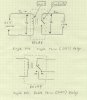
Look at a simple single pole, single throw (SPST) relay. You can see from the schematic below that the contacts look like a simple switch. This is the same concept used for a simple light switch in your home.
If you wanted to use a relay for controlling a light you can just wire the “hot†side to one side of the contacts, then the other to the light itself (the exact same way as a light switch).
Now let’s look at a single pole, double throw (SPDT) relay. You can see that now we have three connections from the contacts; “Câ€, “NO†(normally open), and a “NC†(normally closed). This relay is more versatile than the one above as you can “break†then “make†connections to your load(s). This is also handy if you wanted to use a relay for “source†selection.
Here is an example of where you would want to use a SPDT type of relay. Let’s say you have a wall plate with a red and green LED (light emitting diode) mounted on it. You want the green LED to light when your garage door is closed and the red LED to light when your garage door is open. For this example let’s say you have an Elk M1 Gold (though this is not needed and you could wire the garage door’s magnetic contacts directly to a supply and coil). You would connect one coil lead to an output (say M16) and another to the output ground. You would then connect the “C†lead of the relay to a 12 volt source, the “NC†lead of the relay to the green LED, and the “NO†lead to the red LED.
I’m already assuming that you monitor the garage door via magnetic contacts that are connected to an Elk zone input.
Now you can just create a rule so if the Elk zone for the garage door monitor is “violated†turn output M16 “on†(and create a rule that if the garage door is “normal†turn output M16 “offâ€).
Since the green LED is connected to the “normally closed†contact lead it will be on whenever the relay is “off†(i.e. no voltage applied to the coil). As soon as the M16 output gets activated it will apply voltage to the coil, turn the relay on, and switch the “C†lead from the “NC†to the “NO†contacts, thus turning on the red LED and turning off the green LED.
As you can see a SPDT relay is more versatile than a SPST one. Of course if you only wanted to use a SPDT relay as a SPST you would just use the “C†and “NO†contacts.
Well, that’s an abridged dialog of how relays work relating to home automation control. As for your question on wiring, it would all depend again on the voltage and current ratings of the load. If it is truly low voltage I would guess that 20 gauge wire would be sufficient, but again, check this with your actual load ratings.
As far as the relay location, I don’t see much difference in either way (for low voltage applications), though it would be a lot more convenient to keep the relay inside the Elk box. Of course if you were controlling 120 volts and large currents, it might be a benefit to locate the relay at the load, that way you can keep the 120 volts out of the Elk box altogether.
 h34r:
h34r: