ingfraleometeo
New Member
Hi folks,
Inside 1-wire section in WD I can see that everything is installed and recognized properly
******Searching for Weather station sensors****
******Searching for Weather station sensors part 2****
Humidity type i-button found, ID E5000000B64A1E26
***5th Humidity or solar i-button allocated to, ID E5000000B64A1E26
Leaf or soil i-button found, ID B800001195789A30
***Leaf i-button allocated to, ID B800001195789A30
Switch (windspeed or rain or lightening counter) i-button found ID 3C0000000C918C1D
***Lightening detector found and allocated: 3C0000000C918C1D
Leaf and Lightning sensor work well, I have a question about Solar sensor used with solar CLD240.
As i have no external power but only parassitic I removed the jumper on the board.
When I see Solar Setup of 1-wire WD I see always same value of 249.700 mv despite of day or night. That value remains constant during the whole day.
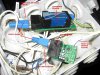
My daisy chain is like the following:
leaf sensor ---- lightning sensor ----- solar sensor -------- 1 wire to USB adapter ----> PC
Is it correct that mv value of solar sensor is always the same all along the day ?
I have made some more check
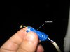
I have isolated solar sensor , so no daisy chain but only solar sensor connected via USB adapter to PC and i get same behaviuor : always 249,700 mv despite of day and night. Only when i disconnect sensor from solar board i got 0.00 mv but it is right due to signal absence.
I verified all connectors and wiring and it is all ok...can't understand where is the fault...maybe the solar sensor board is broken or the CLD240 itself ?
Any idea about ?
Thanks
Francesco
Inside 1-wire section in WD I can see that everything is installed and recognized properly
******Searching for Weather station sensors****
******Searching for Weather station sensors part 2****
Humidity type i-button found, ID E5000000B64A1E26
***5th Humidity or solar i-button allocated to, ID E5000000B64A1E26
Leaf or soil i-button found, ID B800001195789A30
***Leaf i-button allocated to, ID B800001195789A30
Switch (windspeed or rain or lightening counter) i-button found ID 3C0000000C918C1D
***Lightening detector found and allocated: 3C0000000C918C1D
Leaf and Lightning sensor work well, I have a question about Solar sensor used with solar CLD240.
As i have no external power but only parassitic I removed the jumper on the board.
When I see Solar Setup of 1-wire WD I see always same value of 249.700 mv despite of day or night. That value remains constant during the whole day.
My daisy chain is like the following:
leaf sensor ---- lightning sensor ----- solar sensor -------- 1 wire to USB adapter ----> PC
Is it correct that mv value of solar sensor is always the same all along the day ?
I have made some more check
I have isolated solar sensor , so no daisy chain but only solar sensor connected via USB adapter to PC and i get same behaviuor : always 249,700 mv despite of day and night. Only when i disconnect sensor from solar board i got 0.00 mv but it is right due to signal absence.
I verified all connectors and wiring and it is all ok...can't understand where is the fault...maybe the solar sensor board is broken or the CLD240 itself ?
Any idea about ?
Thanks
Francesco