You are using an out of date browser. It may not display this or other websites correctly.
You should upgrade or use an alternative browser.
You should upgrade or use an alternative browser.
Sonesse RS485 Shades and HAI Challenges
- Thread starter HomeTechNewbie
- Start date
HomeTechNewbie
Member
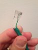
I will try that. Limits were set by the guy that installed the blinds... No clue if they are right though... I can debug that according to the earlier post... i have made a make shift cable of pin 1 and 2 with Green / Green white on both sides.
As requested here are a slew of pictures to see if it helps (just off of one my websites, since i couldn't figure out how to attach images)....Thanks guys! We just might get there, I have faith! ;-). Let me know if you need any others and i will post up.
http://www.hsaleslink.com/pictures-of-smarthome/?preview=true&preview_id=528&preview_nonce=7b9228fdaf
HomeTechNewbie
Member
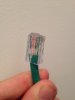
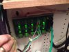
As far as the pinout goes, check out the picture, but its a 6 pin (RJ11 I think) with it in pin #1 and 2. (Pin 1/2 being the ones on the right hand side with the tab facing up)
I cannot access your pictures: "You do not have permission to preview drafts." You can attach images to the post via "More Reply Options". The pinout you describe sounds like a correct one. It will provide straight connection to the motor from HAI port. There are only 2 possible combinations, I suppose you have tried both in case A and B are mixed up? And you do have House Code Format set to "Somfy ILT" for the motor units?
az1324 said:When you say pins 1 & 2 don't you really mean pins 4 & 5 of a standard RJ-25 pinout. I guess you could consider them the left two wires of a 4-wire RJ cable with tab up but AFAIK that doesn't conform to any numbering standard in use.
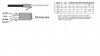
Here is a diagram from HAI:
Attachments
HomeTechNewbie
Member
Oh ok that's strange they would use that numbering on that graphic. On a HAI KB article they list it as a standard DB-25 pinout with pins 4 & 5 (which are the same pins). But I think it is better to stick to standard pin notations.picta said:Here is a diagram from HAI:
I can't tell from the photo posted if the HAI end of the cable is wired properly or not.
There is nothing that stands out as incorrect on your pictures. Have you tried a single motor directly connected to HAI port? If that does not work, you should get a limit setting tool, and use it to operate the motor directly from it. That will eliminate RS485 and you will know if the power is connected and the limits are not preventing the motor to rotate.
HomeTechNewbie
Member
When you talk about single motor connected, I'm assuming you also mean connecting the power cables as well? A/B to A/B and Positive / Negative to power distribution panel... (hence not sure how i would know its working....)
Im sure its going to be something really stupid after all this....
1. Ive called the guy to see if he actually set the limits.. I am trying to borrow his limit tool to double check...but he swears he did...
2. Tested two different serial ports (changed jumper to 485 (which I'm assuming is pin 2 and 3)
3. Created 2 cables in (slot 1/2 on both) and (5/6 RJ11) and 7/8 (just in case i misread it upside down)
4. Checked wire for communication on both ends. all set.
5. Using Virtual Port (USB to Serial) tried to connect to motor. Connected but not reading anything... Wired this way... (See screen shot)
6. Calling Ingersoll and SOmfy next....
Signed, Frustrated....

This is the standard RJ-11 pinout looking into the jack. If you are using a 4-pin version then it uses the middle 4 pins (2-5). So just to make sure with all the different pin notations in this thread, unclear photos, and you said you are using a 6-pin cable, you should have pin 1 of RJ45 to pin 5 of RJ-11 and pin 2 of RJ-45 to pin 4 of RJ-11.
az1324 said:
This is the standard RJ-11 pinout looking into the jack. If you are using a 4-pin version then it uses the middle 4 pins (2-5). So just to make sure with all the different pin notations in this thread, unclear photos, and you said you are using a 6-pin cable, you should have pin 1 of RJ45 to pin 5 of RJ-11 and pin 2 of RJ-45 to pin 4 of RJ-11.
Good point!
HomeTechNewbie
Member
Thanks.
Happy New Year everyone and hears to fixing every DIY project in 2014.
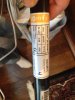
After re-reading, double checking every wire and connection multiple times, I can only conclude that the installer did not set the upper and lower limits of the motor/shade with the limit setting tool. The installer was a bit clueless to this whole automation thing so it would not surprise me. And everything I read, is if that doesn't get set, your out of luck until that is hard programmed into the motor. So with that, I think the last thing to check, is that... and it appears the only way to set limits on these shades is through their Limit Setting Tool. Product Number 9050280. IF there is a work around, please let me know before I spend another 85 bucks on the testing tool....
Thanks for all the help. You guys have been extremely helpful debugging.
Happy New Year everyone and hears to fixing every DIY project in 2014.
After re-reading, double checking every wire and connection multiple times, I can only conclude that the installer did not set the upper and lower limits of the motor/shade with the limit setting tool. The installer was a bit clueless to this whole automation thing so it would not surprise me. And everything I read, is if that doesn't get set, your out of luck until that is hard programmed into the motor. So with that, I think the last thing to check, is that... and it appears the only way to set limits on these shades is through their Limit Setting Tool. Product Number 9050280. IF there is a work around, please let me know before I spend another 85 bucks on the testing tool....
Thanks for all the help. You guys have been extremely helpful debugging.
Happy New Year!
You can get the limit setting tool for $35 here: http://www.avoutlet.com/index.php?dispatch=products.view&product_id=4488. Is is good to have especially for your number of motors.
Also, if you have USB to RS485 (not just RS232) adapter you can use Somfy software to set the limits. You can also use this software to assign motors to groups. I actually have a computer connected to Somfy RS485 network via such adapter, that allows me to control shades from other remotes.
Once you finally get your shades connected and automated, you'll really love them and hopefully forget the frustration")
You can get the limit setting tool for $35 here: http://www.avoutlet.com/index.php?dispatch=products.view&product_id=4488. Is is good to have especially for your number of motors.
Also, if you have USB to RS485 (not just RS232) adapter you can use Somfy software to set the limits. You can also use this software to assign motors to groups. I actually have a computer connected to Somfy RS485 network via such adapter, that allows me to control shades from other remotes.
Once you finally get your shades connected and automated, you'll really love them and hopefully forget the frustration
HomeTechNewbie
Member
Thanks Picta.
Fortunately and unfortunately i do have one of those cables (USB to Serial) http://www.mouser.com/ProductDetail/FTDI/USB-RS485-WE-1800-BT/?qs=sGAEpiMZZMsgSGrx0WqTbGAkhvJAByZv and have connected the wires as following:
On FTDI Cable --> Somfy RS485 Cable
Orange (Data+ A)--> Red (Data+)
Yellow (Data+ B) --> Black (Data-)
All others left unattached.... The software can not read it... (I've tried both 4800 and 9600 baud...). I know its reading the Com port, but no information is coming back from the motor....(e.g. no pulse data, no motor label, etc)
Similar threads
- Replies
- 1
- Views
- 239
- Replies
- 0
- Views
- 1K
- Replies
- 7
- Views
- 9K