Temp sensor room best location

DavidB

Member
Hi, just ran across Hobby Board yesterday while looking for information on how to start monitoring my house with 1-wire. Great site, it helped make my decision to use 1-wire for most of what I want to do rather than X10 (I still might use X10 for controlling lighting in a few places).

First I am going to start monitoring temperatures around the house and outside, maybe add a humidity sensor in/out of house, then use the relay board & hvac monitor to possible control the hvac unit (my work schedule just doesn't work with the programmable thermostat (or at least the one I have)).

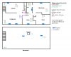
My big dilemma before actually getting my parts is where to place the room sensors.

My first thought was running them thru the basement to each room and another branch thru the attic. Then take the average temp of the two in each room to get a more accurate picture. But that just seems like overkill, so dropped that. Note: I'm not planning on moving any time soon, but do like to plan my projects for future owners or for easy removal.

So I figure can run them thru the basement to the rooms to possibly the outer edges of the room and either just pop the sensor thru a small hidden hole, or even possibly in a small inconspicuous box. Or if the ceiling was the best, thru a small hole and possible paint sensor white. I would think the floor would be the best cause it is generally closer to where people are.

Then wondering also if I really need to do every room?! The kitchen and livingroom are open to each other thru an shuttered half wall to the hallway where the thermostat is. I was thinking of putting two sensors in the basement at each end cause it covers the whole house. Also putting one in the attic to track the efficiency of the insulation and for the HVAC in the plenum leaving the blower (that way can actually monitor the temp of the air leaving the unit to see how well it is working, not just if it is on by monitoring the blower voltage.)

* So what are you guys thoughts on the best locations for room temp sensors?

Thanks, Dave
 
Like this?

temp_20071106.jpg


Still trying to figure out where to put the indoor sensors. There's really no good place for them. Ideally you'd want the temperature at the center of the room. I'd stay away from outside walls, things that create heat (TV, computers), where the vents blow on them, etc. I'll probably do something similar, like poke the ds18s20 out of the wall about 3 to 4 feet off the floor and paint it or hide it behind something. BBQ is going, will say more later.
 
I guess I don't know the best place for the sensor, but about the middle would seem best to me (and of course the hardest place to install) because thats were people will feel the temp. I bookmarked these sensors in case I ever do some kind of one wire sensor
 
I think a better question is where not to place them. Do not place them on outside walls or in direct sunlight. I would mount them about the same height as your thermostat. How many sensors are you planing on installing?
 
Sorry haven't replied yet. I worked all night. Then had to charge my batteries on the meter. Going to take temps all around the house with meter and draw picture so can get a better picture of differences of height and locations. Then maybe we can determine best locations or if even matters. I don't have vaulted ceilings and have newer windows and finished basement so temps are pretty stable and uniform around the house. Will post results and map later today.
 
Well I burned my grilled onions last night.

You don't want the sensors on the ceiling (too warm) or floor (too cold). You want them where the main part of your body is, in the 3' to 5' range.

Unless you've got a zoned HVAC system, you're going to want to pick one sensor to determine if you need cooling or heating. The other sensors could be used for data collection and to answer questions, i.e. if the heat is set at 75, what's the temp in the master bedroom.

I'm working on a similar HVAC control project with Hobby-Boards parts. HVAC monitor is installed and working, if the heat or a/c was on, the plot would be shaded during that time frame. Have the relay board, but haven't installed it yet because I still need to put in at least one indoor sensor (probably where the current thermostat is) and have other projects I'm also working on. You should plan on having a dedicated box for this. I'm using my win server right now, but I'll probably move everything to a separate box in the future.

One thing I discovered was that my ducts are losing a lot of cooling. I have a delta-T of about 15 degrees (directly before and after the evap coil), but the 62degree air coming off the coil gets into the room at 72degrees. And that was mid-september with an outside temp of about 90 and a lower attic (just above the insulation) temp in the upper 90s. During the summer, the lower attic temp was up to 110, but I didn't have HVAC sensors at that time (drats).

Most of the temp sensors that judge_l bookmarked aren't 1-wire, they're 10k thermistor. Most of those could be put together or adapted to use a ds18s20. The "flush mount space sensor" is an interesting idea. It looks like a big screw in drywall anchor.
 
* So what are you guys thoughts on the best locations for room temp sensors?

Depends on where you want to know the temperature ;-)

Example I -- If you want to automate a ceiling fan to convect downward warm air that is 'trapped' near the ceiling during the heating season, you might use two -- one at ceiling height and another at human chest height.

Example II -- If your objective is to be able to estimate the temperature is everywhere in the house, the answer depends in large part on your heating and cooling system design and house construction. In our house, some walls have been retrofitted with new walls and insulation. Others are uninsulated solid brick with no insulation or air spaces at all. The rooms behave very differently and the most effective control is entirely manual: Close the door and stay out ;-)

Example III -- If you have only one HA control available (typically Furnace/AC ON or OFF) then most everything beyond a single well-placed conventional thermostat may be mostly just to satisfy one's curiosity.

Before placing the thermostats, you might follow the 'software before hardware dictum' and write the HA rules ('programming') that you would use to do whatever it is that you want to do.

Then place the sensors accordingly based on the physics that pertain to each rule that you write.

Unless you are planning on Example II (Know everything everywhere all the time) this is the best approach in my experience in monitoring and instrumentation. Sometimes the design and rules are still in your head rather than actually written out/programmed, but knowing what actions will be taken based on the data in each room is key to not having to go back to install more stuff or worse, getting wrong or useless answers.

... Marc
 
Thanks for all the replies! I have a map attached now of the house, with temps at ceiling, middle, floor for upstairs. Then basement and attic and outside. Ceilings are 8 foot.

The temps only vary from ceiling to floor about 2 degrees F. and the thermostat appears to be reading 2 degrees low. Looking at this picture I really don't see a problem mounting the sensors at the floor from the basement. Which would be much easier. I have done enough wall cutting over the years and don't really want to run the 1 wire thru the walls and up to mid level. Especially when it is only about 1 degree diff. Even the basement (which doesn't have insulated walls but is just concrete) is right around the thermostat setting. The Master bdrm and corner bdrm might be a tad warmer cause have a heated waterbed and the other is the computer room.

Outside temp right now is 48.8 away from the house. When mount a sensor out there probably going to take it from the back eave, so measuring there it is about 4 degrees higher and the attic center about 4 more. So looks like my attic insulation is doing okay because is only approx 8 degrees higher than outside away from the house and center of house is 21 degrees warmer than outside and I can't remember last time I heard furnace kick on. So I think I can mount the sensors from the basement and stick up in a out of the way location around the house. If I decide to control the hvac with it I would still use the hallway sensor reading. And keep the sensors away from the registers.

sda Grilled onions. Never thought I would like them, but have friend that puts them in foil and a pad of butter and cooks them. Liked them enough that I started doing it. Let me know when you don't burn them so I can drive over. :D
Yes, I am planning on using DS18S20 also for this project. And graphing them similar to the way you did it. Are those 'Return' values from your return vents?
Unless you've got a zoned HVAC system, you're going to want to pick one sensor to determine if you need cooling or heating.
No, single point in hallway, probably use the same location for controlling the hvac.
You should plan on having a dedicated box for this.
Yes, I have a server I use for a family/friends picture gallery running Gentoo Linux. Was planning on using that. It doesn't see a lot of action so have spare capacity for use and it is on all the time.
One thing I discovered was that my ducts are losing a lot of cooling.
That is something I am going to check out also, but didn't do it for the map just did. When put the sensors in place I am going to put one in the plenum leaving the blower. I think that is a good way to actually see how well the unit is performing. You can monitor the blower,... but knowing what the house temps are vs outside and then looking at the actual air leaving right after the unit really helps to see how well it is performing. Then I can check room temps while graph shows it running to see how the duct work is performing. Not too much of a problem in the winter cause heat rises. But would like my cold air in the summer to visit me upstairs. :lol:
Most of the temp sensors that judge_l bookmarked aren't 1-wire, they're 10k thermistor.
I might use X10 for controlling some lights and camera, but am doing this monitoring and hvac control with 1 wire.

judge_l
I guess I don't know the best place for the sensor, but about the middle would seem best to me (and of course the hardest place to install)
You got that right and I really don't want to do that. Did enough of that cutting,.. when re-wiring my house. I think based on my map I can safely get good measurements from the floor even if I add a 1 degree fudge factor.

toymaster458
I think a better question is where not to place them. Do not place them on outside walls or in direct sunlight. I would mount them about the same height as your thermostat. How many sensors are you planing on installing?
The inside of my house doesn't really get much sunlight inside. Wish it did so I could grow a few plants. I got a philodendron growing, but it has to be in the kitchen or I don't think it would even get enough light. I'm not sure how many I plan on installing yet. I was originally planning on every room, 3 in the basement (each end and plenum) and one in attic and outside. It looks like I could get an accurate picture of the left side with just one sensor. But I think I will still install one in every room. I like to monitor stuff and lets say I leave a window open in the livingroom during the day, forget and notice on graph that that room temp is dropping cause got cold. Hey window is open stupid. :) But I will still have only one control for the hvac and that will be in the center of house.

hult
Example I: Think going to just stick with monitoring and one control point for the hvac. Which I might add later to web interface to turn hvac cooling/heating if need to.
Example II: Yes, I noticed things when did the map of the house temps. I have a brick front that is insulated and left side of house and back to the bathroom have new insulation. Attic new insulation. Rest is original something like R7.5 I think. But I could see also that the computer room and waterbed caused the right side to be warmer. But yes, I want to monitor as many points as possible and not get crazy with it. I think one per room is pretty reasonable and the DS18S20 dont' cost that much.
Example III: LOL, really the whole project is to just satisfy my curiosity. And I haven't really tinkered much over the years since college. Got into wood carving, made some cool carved cradles for one of my brothers kids,.. scuba diving,.. Now want to tinker with some home automation, but keep is somewhat simple and sane. Plus, I might see a pattern or something that will point out a problem with my energy use and fix it.

Yes on the last. I do have a tendency to do that sometimes. That is one of the reasons I am starting off with just temp sensors and not control. And mapping the house temp ranges out to see what is feasible and reasonable to do and last but not least placement. And drum roll, getting ideas from others that have a similar interest/experience with this. Then I will sit down and draw up everything before I actually put it in place. That still doesn't always cover every situation, but helps.


***********************
So since I have said that I don't see a problem according to 'my house' with the temp sensors at floor level, but away from registers and outerwalls. Looking at the map temps do you think I am wrong? Maybe I am missing something?
 

Attachments

  • HouseTemps.jpg
    HouseTemps.jpg
    81.1 KB · Views: 74
Okay, the passion subsides and reality sets in as I actually looked for spots to put the sensors.

I have hardwood floors in the bedrooms and vinyl in the bathroom and kitchen. I can still mount near the floor believe, but will have to come up over the trim work. So going to look into some type of box or small enclosure to make it look nicer.

Another idea. I have phone/ethernet jacks in 3 rooms (corner bedrooms and kitchen). Would need to add one to the frontroom and middle bedroom. The kitchen and master only have phone jacks, so could change these to those 2/4 port plates and get some of those blank inserts for the holes. Drill a hole in middle of the insert and put the sensor in there with a little silicon. I was going to take a picture to put up, but loaned my camera to a friend for his ebay stuff.

I think that will take care of the attractiveness issue, the wall plate will have extra inserts spots if I want to wire it up later for phone or ethernet also. Then it is not exactly thermostat level, but is off the floor. And according to the temp map of my house, that should work accurately enough. I have a buddy with a 3 or 5 ft flexible drill extension also, so can just cut the hole in the rooms I need to add this to and won't have to judge where the wall comes up from the basement in those rooms.

I am sure you guys know what I am talking about, but until I get my camera back this is plates talking about: Wall Plate to mount temp sensor in.
 
DavidB-

Nice temp map and good idea. Another idea that came to me was to measure the temp at the center of the room or where you occupy the room, then pick a sensor location based on that measurement. A suggestion is to put all sensors at about the same height. That way you won't have to make mental adjustments for "that room is reading colder because the sensor is near the floor".

Home Depot sells the Leviton quickport stuff. Another thread discussed putting a sensor right into an RJ45 plug and crimping it. Haven't tried that personally, but I dry fitted one. The DS18S20 fits entirely inside the plug and is open to the air.

Another idea I'm thinking about is replacing a standard single gang switchplate with a double gang. The sensor would be mounted behind the other side of the plate. You can get standard combo plates with a switch/hole in them (typically for switch/rotary fan controls), or drill it. Decora plates have similar inserts. Drill a 1/2" hole in the wall, fish the cat5 wire, connect the sensor, and caulk it in the wall with the head exposed. Add a bit of black mesh over the plate hole on the back side of the plate.

I think the more you try to hide the sensor, like putting it in a box, the more visible it will get. Since the sensor itself is only the size of a pencil eraser, "something" inserted flush to the wall and painted might be less noticeable. I'm still looking for "something", which doesn't need to be bigger than 1/2" diameter.

I'm also thinking about how to rip this stuff out when I move. Buyers get flaky when there's things they don't understand. I could leave it in place as a selling feature, but I don't want another "customer" to support.

I'd suggest a hobby boards hub and power supply. Locate the hub centrally and run a cable from your server to it. You might want to run a second cable back to your desk for testing, or get another adapter. Group sensors together by function (indoor, outdoor, hvac control, ducts, etc) and put them on separate hub ports. Makes the wiring easier and you can work on one segment without taking out the whole network.


"Are those 'Return' values from your return vents?"
Yes, I have sensors in the two returns (Return Hall, Return Office) just above the filter. When the AC is running this will be the temp of the air being pulled into the system. These two duct runs join in a plenum under the rooftop unit. (Return Main) is the temp in the unit just before the evap coil. (Supply Evap) is the temp just after the evap coil. When the unit is running, (Return Main) - (Supply Evap) is the Delta-T. (Supply Main) is another sensor on the other side of the unit, below the heating tubes, where the air enters the supply duct plenum. For the few hours in September when I ran the AC, I was losing 3 degrees of cooling before the air even left the roof, and 10 degrees by the time it got into the rooms. And that was on a 90degree day when the lower attic temps (Plate Line) was mid 90's. In the summer, the lower attic temps were above 110. The (Ceiling) sensor is in the attic under the insulation and taped to the sheetrock ceiling. It shows that the insulation is doing its job.
 
sda
Yes, that is what was thinking about using a blank quickport, see picture. Drill hole and put in a blank one. Get a 2 or 3 port plate and the others could be wired up for lan or phone. Have the head of the sensor fixed into the hole. Might have to test it to make sure with just the head surface showing if that is correct reading. So won't silicon in place till test that out. Might also try fitting one into a RJ45 plug, that would hide it and leave it open to air like you mention.
BlankQuickPort.jpg

I'm also thinking about how to rip this stuff out when I move. Buyers get flaky when there's things they don't understand. I could leave it in place as a selling feature, but I don't want another "customer" to support.
Thought about that also. That is one of the reasons for using the quickports. There could be lan and phone connections there also. I don't want to support it either, so my stuff could be ripped out and leaving the quickports in place with the phone and lan connections makes it easier to just leave that stuff and remove only the 1-wire stuff.

I'd suggest a hobby boards hub and power supply. Locate the hub centrally and run a cable from your server to it. You might want to run a second cable back to your desk for testing, or get another adapter. Group sensors together by function (indoor, outdoor, hvac control, ducts, etc) and put them on separate hub ports. Makes the wiring easier and you can work on one segment without taking out the whole network.
I ordered a 6 channel master hub, 4 DS18S20, power supply to start with. That was going to be the first branch. And might later be used to control the hvac, cause it was going to be the hvac plenum, temp where the thermostat is, attic and outside. I will probably put the actual hvac control on seperate branch though. I decided on that group first cause it will be a straight run pretty much from the hub and up thru the pipechase and to outside. Going to be a little hard getting the wire from the thermostat to that, might have to disconnect it and tie a fishing line on it, then pull it out and back up to get my new wire into the hole.

I was thinking about the location and my use also. The ones that are wired with quickports already are in good locations. The other ones I will keep that in mind, because I agree that it should be where I use the room most.

Thanks for all the suggestions. I'm not sure how long it takes hobby boards to get the products out. I ordered Thursday. So when get them going to do a quick temp sensor connection to a cat5 wire with a RJ45 crimped together and make sure it all works. Then start running my line. I was looking at the RJ45 wiring on the hobby board site and vs the schematics and they seem backwards. Going to make sure I ring out the board first to see how the connections are before crimping my RJ45,..

Are you running separate power to the DS18S20 or connecting the ground and Vdd? I haven't seen any definitive proof one way or the other of which is best.
 
DavidB
Yes, that is what was thinking about using a blank quickport, see picture. Drill hole and put in a blank one.
Good idea and clean looking. Maybe you can find something to mount the sensor in. Super glue a small plastic bottle cap to the back of the insert? Hot sauce bottle cap s/b about the right size.

DavidB
I'm not sure how long it takes hobby boards to get the products out. I ordered Thursday.
Eric has been pretty fast. My stuff has come in just a few days and I'm in California.

DavidB
I was looking at the RJ45 wiring on the hobby board site and vs the schematics and they seem backwards.
Its plain old 568A wiring. If you look at the diagrams, the drawing on the left is looking at the front of the plug. The drawing on the right is looking at the front of the jack. The plug turns 180degrees to plug into the jack. The pinouts on the schematics are jacks. The jacks are pins down on the schematic and pins up on diagrams, which might be why they seem backwards to you. Never paid any attention to that until now.
http://www.hobby-boards.com/catalog/howto_..._connecting.php

DavidB
Are you running separate power to the DS18S20 or connecting the ground and Vdd? I haven't seen any definitive proof one way or the other of which is best.
Separate power.

What I've found is that if you run them in parasite mode, it has to draw power from the bus when doing the temp conversion and the bus is unavailble during that period. In powered mode, the sensors draw power from vdd and other activity can happen during the conversion.

It takes "about" a second for the sensor to get the temperature, whether parasite or powered. You send a temp conversion command, wait until the sensor is done, then read the temp. Take a look at the data sheet for details.
http://www.maxim-ic.com/quick_view2.cfm/qv_pk/2815

This is no big deal if you've only got a couple of sensors to read. I have about a dozen sensors and will be adding more. I read my sensors every 15 seconds and take the average for each minute. In powered mode, I turn on a hub port, send a temp conversion command to each sensor on that port, then go back and read each sensor in the same order. By the time the first sensor is done with the conversion, the rest are also. It takes 1 second to read 10 sensors vs 10 seconds to read 10 sensors.

Parasite vs powered may be a push. I need powered for what I do, but I developed my own software and canned packages may not support this. Powered may also improve reliability, but I have nothing to back that up with except from my own experience. I read each temp sensor 5760 times per day (4 times per minute * 1440 minutes per day) and rarely get a temperature conversion error.
 
I actually replied yesterday, but not sure what happened to the post!? So here goes again.

I actually like the idea you mentioned about using a RJ45 quickport to put the sensor in better. I think it is easier also. Will look into it.

This is the problem talking about with the schematics vs the networking information. Taken right from the howto_wiring_diagram page and schematic of 6 channel master hub.
Jack_Schematic_diff.jpg
In reality it doesn't matter as long as you do the same colors at both ends of the cable (if your plugging them in to a jack and not just tapping into the cable for each sensor drop), I'm sure we both know that. Cause it is a straight thru cable. But it could make troubleshooting harder later if you don't pay attention. Granted, I find errors or omissions in schematics freq. But in my job I have to work around them or correct the schematic so I know next time.

Glad he is fast. I hope to get them on my weekend, which is wed, thur, fri, sat. I work a weird schedule. Can't wait to play with it. Still says processing on the website.

I'm not planning on reading the sensors as freq as you are. But was thinking of doing powered mode also. Actually since I am getting the 1A transformer and the master hub, I was thinking of using the 5v off there to power them and tie each sensor leg to correct wire. Then if decided to change to parasitic I can just cut that wire somewhere near the hub and tie it to the sensor return. Just an idea. I read that the max amps the sensors 'might' draw is: However, when the DS18S20 is performing temperature conversions or copying data from the scratchpad memory to EEPROM, the operating current can be as high as 1.5mA.
So I should be able to cover all my sensors plan on putting and more and I don't think any of my drops are going to be long enough to cause a voltage drop problem.

*Oh, I do have a new question. I just looked at the computer going to be using and has 2 serial ports, so doesn't matter as much right now. But has anyone used the X10 CM17A and 1-wire? It is suppose to be a thru port. But it does mention if using the serial port for constant monitoring,.. of something else it would be better to use another port. I was just wondering cause my main computer has one serial port, so it could become an issue in the future. I guess I could switch to a usb adapter if had to for one of them, if possible in the future.
 
This is the problem talking about with the schematics vs the networking information. Taken right from the howto_wiring_diagram page and schematic of 6 channel master hub.
View attachment 1325

David,

When I laid out the schematics I wasn't thinking about the ordering of the pins for the RJ45 but if you look at the pin numbers on the schematic they match the wiring diagram. Sorry for the confusion.

BTW Your order will ship out today. It would have gone out yesterday but the post office was closed.

Eric
 
Back
Top