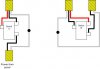
Ok, maybe not all electricity, but at lest residential wiring. I've started replacing my light switches with SA UPB ones and have a question on a 3-way circuit of course. Attached is a diagram of the circuit in question. I want to put a US2-40 controller with the rocker and 4 button faceplate at switch B location. I've identified the power for the circuit comes in at switch A where I'd like to put one of the remote USR switches. With only one diagram in SA's instructions (and not like my configuration) I'm at a loss on how to wire it up. Can any of the capable UPB folks help?
Thanks,
--Jamie
Jamie,
First turn off power to that switch..
")
You will wire the black from the panel to the black on the USR switch AND the black going to location B,
And
You will wire the White from the panel to the white on the USR switch AND the white going to location B
You will wire the Ground from the panel to the Ground on the USR switch AND the Ground going to location B
The Red will be the remote wire. Wire this up to the remote 1 wire on the USR
In Location B
You will wire the black from location A to the black on the US2-40
And
You will wire the White from location A to the white on the US2-40, and the white wire going out to your fixture
You will wire the Ground from location A to the Ground on the US2-40and the ground wire going out to your fixture
Next connect the red wire from location A to the remote 1 wire on the US2-40 in location B.
The Brown wire is the hot wire output to your fixture
* Some versions of US1 and US2 models used “traveler†wires instead of the “Remoteâ€
HTH
")