All,
Wondering if this will work before I order the equipment:
I would like to be able to control some outlets located in the same utility closet as my Elk M1G (only one outlet per circuit, as they are used only for automation) WITHOUT using any third-party devices such as Insteon, UPB, etc. In fact, my initial need for this is to be able to "reset" my Insteon PLM (used with Homeseer) when the blasted thing locks up. However, I think I could also use this to reset my router if necessary, even if it were plugged into an Uninterruptible Power Supply (a UPS, which filters most powerline signals that could be used on an alternate technology plug-in device like an X10 appliance linc).
Here's my plan:
1) Connect an Elk-M1RB relay board OR a relay on an Elk-M1XOVR, OR an Elk-912 or 912B directly to the M1G (would really like to know if any or all of these would work for the purpose below, please).
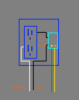
2) Wire the AC power neutral leg directly to the outlet to be controlled, as is normal.
3) Wire the hot leg through one of the relays above, as a normally closed circuit, before connecting to the hot side of the outlet. The power line draw for either a PLM or a router would be much, much less than the rated 10A @ 125 VAC of these, correct?
4) IF the Insteon PLM locks up on me when I'm away (has happened, and shuts me down for lighting control), I could just turn on the respective Elk output for 30 seconds via the web using the M1XEP, which would open the circuit and allow the Insteon PLM to reset.
4a) The same could be done via either Homeseer or possibly even Elk Rules for the router if a ping failed repeatedly, except I'd plug this type of "outlet" into the UPS.
So... Is this something so obvious I should have seen it long before this? Are others doing it? Unless I completely misunderstand the use of these relays, it seems one could have hard-wired on / off control of outlets / circuits located very close to the M1, creating a good method of resetting other automation devices.
Am I missing something here? Do I misunderstand the use of these relays? Or can I just do it?
Thanks,
Joe
Wondering if this will work before I order the equipment:
I would like to be able to control some outlets located in the same utility closet as my Elk M1G (only one outlet per circuit, as they are used only for automation) WITHOUT using any third-party devices such as Insteon, UPB, etc. In fact, my initial need for this is to be able to "reset" my Insteon PLM (used with Homeseer) when the blasted thing locks up. However, I think I could also use this to reset my router if necessary, even if it were plugged into an Uninterruptible Power Supply (a UPS, which filters most powerline signals that could be used on an alternate technology plug-in device like an X10 appliance linc).
Here's my plan:
1) Connect an Elk-M1RB relay board OR a relay on an Elk-M1XOVR, OR an Elk-912 or 912B directly to the M1G (would really like to know if any or all of these would work for the purpose below, please).
2) Wire the AC power neutral leg directly to the outlet to be controlled, as is normal.
3) Wire the hot leg through one of the relays above, as a normally closed circuit, before connecting to the hot side of the outlet. The power line draw for either a PLM or a router would be much, much less than the rated 10A @ 125 VAC of these, correct?
4) IF the Insteon PLM locks up on me when I'm away (has happened, and shuts me down for lighting control), I could just turn on the respective Elk output for 30 seconds via the web using the M1XEP, which would open the circuit and allow the Insteon PLM to reset.
4a) The same could be done via either Homeseer or possibly even Elk Rules for the router if a ping failed repeatedly, except I'd plug this type of "outlet" into the UPS.
So... Is this something so obvious I should have seen it long before this? Are others doing it? Unless I completely misunderstand the use of these relays, it seems one could have hard-wired on / off control of outlets / circuits located very close to the M1, creating a good method of resetting other automation devices.
Am I missing something here? Do I misunderstand the use of these relays? Or can I just do it?
Thanks,
Joe
")