You are using an out of date browser. It may not display this or other websites correctly.
You should upgrade or use an alternative browser.
You should upgrade or use an alternative browser.
12VDC to 9VDC stepdown
- Thread starter rfeyer
- Start date
CAI_Support
Senior Member
You may want to add a diode for removing reverse spikes motor likely to generate, also increase the filter capacitor size to filter possible noise generated on power line by motor.
Desert_AIP
Senior Member
I use an inexpensive board I got from e-bay to step down the 12VDC in my enclosure power supply down to 5VDC to run my RUC.
I think it was less than $5 and infinitely less fiddly than rolling my own. It has a wide range of input voltage and an adjustable output voltage.
I think it was less than $5 and infinitely less fiddly than rolling my own. It has a wide range of input voltage and an adjustable output voltage.
:hesaid:
Either one of these will do what you need. The second one includes a built-in voltmeter.
www.ebay.com/itm/DC-DC-LM2596-Step-Down-Adjustable-Converter-Power-Supply-Module-1-3V-35V-F5-/291362318499
www.ebay.com/itm/DC-DC-Buck-Step-Down-Converter-Module-LM2596-Voltage-Regulator-Led-Voltmeter-/160995621268
Amazing the inexpensive choices!
AS I am a beginner and obviously still learning about electronics, I will go with making my own board - I need all the experience I can get, but thank you all!!!
Will apply the diode and increased cup and then repost the diagram unless other ideas spring up in anyone!!
TY again for the replies so far,
Rainer
drvnbysound
Senior Member
I've done similar in automotive applications with a simple voltage regulator (12V to 5V in my case).
Here's an example of a 9V model:
http://www.mcmelectronics.com/product/NTE1966
... and it's datasheet:
http://www.mcmelectronics.com/content/ProductData/Spec%20Sheets/NTE1966.pdf
Here's another:
http://www.mcmelectronics.com/product/NTE1957
Here's an example of a 9V model:
http://www.mcmelectronics.com/product/NTE1966
... and it's datasheet:
http://www.mcmelectronics.com/content/ProductData/Spec%20Sheets/NTE1966.pdf
Here's another:
http://www.mcmelectronics.com/product/NTE1957
TY kindly, drvnbysound,
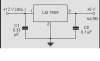
I actually do have the LM7809's in the original diagram - question: is the original diagram sound? i.e.: does it look like it should work without burning up the WC8
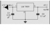
Here is the same diagram with a diode added as requested by CIA_Support - would this now be usable?
Also, which capacitor would you increase in size and to how much?
TY again for the responses,
Rainer
I actually do have the LM7809's in the original diagram - question: is the original diagram sound? i.e.: does it look like it should work without burning up the WC8
Here is the same diagram with a diode added as requested by CIA_Support - would this now be usable?
Also, which capacitor would you increase in size and to how much?
TY again for the responses,
Rainer
Attachments
drvnbysound
Senior Member
My apologies... I saw the diagram, but didnt look up the LM7809. In my case, I didn't use any caps and used only the regulator - YMMV.
Desert_AIP
Senior Member
The caps help smooth out transients. They aren't absolutely necessary, but good power supply designs usually include them.
Your diagram looks ok to me.
Your diagram looks ok to me.
Manufacturers spec just to stabilise the internal components against transients that the electronics may not be able to respond fast enough to. Most of this is trial and error history. Larger capacitors will not handle fast transients as they usually are constructed f a wound layering that act like an inductance and have high impedance to high frequencies.
A larger capacitor on the output can endanger the regulator when the power supply fails or is removed as it can backfeed lineside components stressing the regulator internal transistors.
What comes to mind is a cigarette lighter plug-in with a USB outlet on it. Rip the guts out of one and wire it up. They can handle anything that happens to a car battery. 9-16 vdc input and alternator and vehicle electrical noise.
LarrylLix said:What comes to mind is a cigarette lighter plug-in with a USB outlet on it. Rip the guts out of one and wire it up. They can handle anything that happens to a car battery. 9-16 vdc input and alternator and vehicle electrical noise.
Your suggestion is a good one. But some of the really cheap USB car chargers contain little more than a LM7805 and a couple of capacitors. The better ones use a switching voltage regulator, such as the ACT4533.
OK, that makes sense and TY.
So, in the above schematic, I could have just as easily used a 1uF on the positive side and a 0.5 (as example) on the ground side? as long as the output side isn't something like 1uF and above?
Will these values then increase depending on voltage and amperage?
Rainer
So, in the above schematic, I could have just as easily used a 1uF on the positive side and a 0.5 (as example) on the ground side? as long as the output side isn't something like 1uF and above?
Will these values then increase depending on voltage and amperage?
Rainer
Similar threads
- Replies
- 4
- Views
- 638
- Replies
- 0
- Views
- 1K