Convert Old Security To Elk M1 Gold

Ed Nelson

Member
Hello all;
First a little background: I approached this and the CQC board about a year ago as green as tomatoes. With advice and a pretty strong autodidact sense
about me, I have been working with the ELK M1G and have developed some pretty elaborate rules and interfaces to Insteon as well as the TS07. Actually, I have the TS07 scrolling through WWW Web Cams on a regular basis including weather. I have also successfully installed a Whole House Audio (Nuvo Grand) and completed a very impressive central wiring closet (everything labels and segment by transport type). I have also moved all equipment
to this closet (which is cooled via a wine cooler air conditioner) and am delivering HDTV in component form over 3 RG6 strands to all rooms.
With that said, I consider myself pretty up to date.

However, I am now ready to replace the currently installed security system with the ELK M1 Gold. This way I can leverage all the existing contact points. The programs I have done thus far has been using the supplied ELK 220 Ohm EOLs to simulate contact open/closes.

My question:

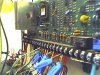
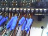
Looking at the pre-installed security panel, I have no idea how to migrate from the existing to my M1G. I thought it would be a matter of toning out the contacts to the control panel in the closet. However, it appears (that like the ELK), once the contact are connected to the controller, they form a closed system and you cannot tone out to a single contact pair. I thought about disconnecting what appears to be a pair, attaching the tone source and running throughout the house to find the contact.

Also, these wires appear to have resistors on them and not just wires terminating from the entry point contacts.

Any experiences, guidance, help on this would be helpful.

I have provided photos of the current security system (which by the way was never activated). My home has:

- Door / Window contact points
- Smoke Alarms
- Wireless Glass Break Sensors in the ceiling

Thanks Guys.

- Ed
 

Attachments

  • Photo_102407_005.jpg
    Photo_102407_005.jpg
    118.8 KB · Views: 60
  • Photo_102407_006.jpg
    Photo_102407_006.jpg
    79.8 KB · Views: 45
Yes, that is an excellent How-To! :lol:

I'll tell you what I would do, but let me start by stating this caveat that I'm NOT a professional installer!

It looks to me that your resistors which are supposed to be at the end of the line (EOL) are terminated at your panel. I would not use them for the Elk.

But, before you cut them off (if you decide not to use them that is) let's get a handle on how they are wired to your sensors. This may be meticulous, but not knowing the state of the wiring, I would want to measure the resistance of each contact pair of wires with a multimeter (contact open and closed). It looks like they used red/black and white/green wire pairs with the black and green as the "common". Hopefully you can just take a pair and measure the resistance between them with a multimeter. The reading should be whatever value the resistor is (if you get a close up shot of the resistor or read off the color code, I'll let you know the value). Anyway, when you open a zone you should get infinite resistance or "open" circuit. This will let you know which wire pairs go with what zones AND also insure you that your wiring is OK.

The motion and glass breaks may be more complicated as they require power for their 'contacts' to work. I would think that a tone ringer would work. Maybe after you know where all your door window contacts go to their respective wires, you can then determine the remaining pairs must go to the glass breaks and motion detectors. You could then send a tone on one of those wire pairs and then use the "sensor" to "sniff" each motion and glass break.

Hopefully you can also tell which wires are glass breaks or motions because their wiring bundle should have "two pairs" in it (two for power and two for the contacts) vs. a single pair in a bundle for regular door/window contacts.

You could then power the system on just to get power to the glass breaks/motions, then measure their contact pairs with a meter as you did with the other sensors (have someone walk in front of a motion or test a glass break while measuring the resistance between the contacts).

When you do wind up terminating the zones to the Elk, I would then cut off the resistors and “defeat” the EOL setting in the Elk program.

Let's see what other ideas some of the professional installers come up with though... :lol:
 
Looking some more at your pics, I'm also now thinking they may have "doubled up" some sensors to a zone. In other words, they might have combined say windows in a room to one zone.
 
Looking some more at your pics, I'm also now thinking they may have "doubled up" some sensors to a zone. In other words, they might have combined say windows in a room to one zone.
Some panels are designed to have multiple zones connected to the same terminal. The zones are differentiated by having a different resistance value for the "EOL". This looks like the case here.

The best way to get a clue as to what is what, is to look at the board schematic before removing any wires. The board schematic is usually pasted onto the back of the front cover. You can determine what wires are on what terminals and look at the keypad zone card to relate the zone number to the physical device. This will narrow it down quite a bit.
 
It looks like you have an Ademco panel there (a Vista 10 or 15, or possibly a Safewatch 3000). Honeywell/Ademco also private labels for ADT.

If you can see any labeling that indicates the panel manufacturer and model number you can get the manuals from somebody (the ones the installers dont leave behind). Also look at teh keypads to determine what is on each zone (ademco puts a label on the inside of the door of the keypads)

If you system is still active you can walk test it and make notes. Have one person look at the keypad as you test each contact, motion etc.

If it is one of the panels I mentioned the first two wires on the left are teh transformer, then I think the bell circuit and then the 4 wire buss. I am going off of memory here and it may be a little corrupted at this point :)

The last 4 terminals on the right would be telco and I forget where the fire power is for 4 wire detectors on those boards (they are almost identical for all 3 models I mentioned)
 
Probably the zones on the old control have the EOL Resistors installed at the control which is a waste of a good EOL Resistor. It does you no good except make your control more susceptable to transient noise.

Remove the EOL Resistors and program the zone definition on the M1 for Normally Closed. You can verify the operation of the zone after you connect it to the M1 thought the keypad zone status. Turn on the Chime for audible annunciation. It should show 0 volts when the circuit is normal or door is closed on user program option 8,6,3.


That would apply for burg but not fire zones correct? The fire would be N/O with EOLR. Ademco and ELk use the same EOLR for 4 wire zones but for 2 wire smokes the ELK is an 820 ohm.
 
My money says Vista20p, A Vista 10 usually doesn't have a #8 and never has #18-20. The 15p has a #8 and supports 2 wire smokes between #8 & #9 but also does not have a #18-20. It appears this one has a #18-20.

I also find it somewhat strange how it's been wired aside from the previsouly mentioned EOL at the control they also were not trimmed back very well. But what I find the most strange is the zones wired in parallel, zones 3 or 4 (#12,13,14) and zones 7 or 8 (#18,19,20) all use 2k ohm when using zone doubling you should use 3k ohm for the first zone and 6.2k for the second.


Does it work properly?


Do you have to open all of the windows in a room to trip it or just a single window?

Vista 20, Safewatch 3000 whats the difference??? :) They are the same board from what I remember but the Safewatch was a branding thing.

Good panels for what they are. No match for an ELK though...... then again not much comes close to an ELK.
 
Maybe I missed the point of the OP. Are you trying to determine the layout of
the wires from the specific sensors to the panel?

Assuming the existing panel is operational, can't you just violate various windows/doors
to determine which wires go to which zones? I don't have experience with too many
systems, but I figure all of them have a way of indicating the zone # that is violated
whenever an attempt to arm is performed.

gk

OP?

Yes we can tell quite a bit from looking at the wires, however we cannot tell exactly what is on the other end.


My query was more questioning if the installer wired a bunch of NC contacts in parallel. If he did you would need to trip EVERY contact on that zone to actually get an alarm.

Yes if it is operational you should be able to just violate a zone and then attempt to arm, the keypad will display the zone violated.


How many Doors/Windows/Motions/Glassbreaks do you have?

You can wire motions and glassbreaks in parallel to keep the falses down. That may be what I am seeing, 2 glass breaks in the same room where both must trip to get an alarm. Same goes for motions, you can put 2 in opposing corners and both must trip to get an alarm.
 
OP = original poster

Again, I have little experience outside of my house. In my case a bank of windows are on a
given zone, so tripping only one would identify which wire was for that zone/set of windows. I think that is the normal way of doing things. Given that, I've only got about 10-12 zones to check, but no glass breaks and the PIR is obvious because it is a 4-conductor wire.

From looking at the picture, I would assume that each window is home run back to the panel, but a given group is wired to the same zone. That's what I guess creates the multiple connections at each zone screw. It seems odd that the installer would have put in a resistor for each of the wires instead of a single one (since he is installing it at the panel). I'd think this would create parallel resistor circuits which would create an overall resistance following: 1/(1/R1 + 1/R2 + ... ) which would not be what the panel expects.

gk

Maybe I missed the point of the OP. Are you trying to determine the layout of
the wires from the specific sensors to the panel?

Assuming the existing panel is operational, can't you just violate various windows/doors
to determine which wires go to which zones? I don't have experience with too many
systems, but I figure all of them have a way of indicating the zone # that is violated
whenever an attempt to arm is performed.

gk

OP?

Yes we can tell quite a bit from looking at the wires, however we cannot tell exactly what is on the other end.


My query was more questioning if the installer wired a bunch of NC contacts in parallel. If he did you would need to trip EVERY contact on that zone to actually get an alarm.

Yes if it is operational you should be able to just violate a zone and then attempt to arm, the keypad will display the zone violated.


How many Doors/Windows/Motions/Glassbreaks do you have?

You can wire motions and glassbreaks in parallel to keep the falses down. That may be what I am seeing, 2 glass breaks in the same room where both must trip to get an alarm. Same goes for motions, you can put 2 in opposing corners and both must trip to get an alarm.
 
Ooops I thought you were the OP. :)

Anyway your windows are probably NC contacts wired in series rather then parallel, thats why any one can trip the zone. Thats also the most common installtion. This is why it's odd to see 4-5 2k ohm resisitors split between 2 zones on a vista20p.
 
Probably the zones on the old control have the EOL Resistors installed at the control which is a waste of a good EOL Resistor. It does you no good except make your control more susceptable to transient noise.

Remove the EOL Resistors and program the zone definition on the M1 for Normally Closed. You can verify the operation of the zone after you connect it to the M1 thought the keypad zone status. Turn on the Chime for audible annunciation. It should show 0 volts when the circuit is normal or door is closed on user program option 8,6,3.

First of all, thanks to "EVERYONE" that responded. This is exactly how I went from clueless to humbly excited. Spanky (Nice hearing from you again since the class...), your response was where I was leaning in the first place. Just pull all of the wires from the current system (which is a Ademco Vista-15P). Once all
the wires are pulled and the resitors removed, I can use a sig gen to fine the contacts/glass/Motion devices and connect and configure to ELK.
 
Back
Top