pete_c
Guru
The roots of said endeavor started in the 1990's -
I was working on this project at various "hubs" (they were around the world). It involved flight vectors based on a Unix application. (display was just a screen with a bunch of lines all over it). The server took data from multiple sources. What was kind of neat was that it was pretty dynamic with real time updates of the vectors. The geographical base and time came from an NTP GPS device the size of a Volkswagon Beetle. I wish I had a picture of it. It looked like a 1955 Chevy with a lot of chrome in its own dedicated room. Think it was called a Megadata beacon digital processor (it did more than GPS) for the Passur system (network-radar). In the late 1990's I wanted a similiar time base for HQ but the GPS that was utilized at the "hubs" was many thousands of dollars and I was on a "budget". Instead I decided to utilize some surplus little non destructive under any circumstance box which I purchased for about $50. It appeared to be built for a tank or some similiar style vehicle. A work peer and I climbed to the roof of HQ (there was access and it was only 4 stories). At the time on the roof were remnants of an old point to point microwave communications link. I remember numerous signs near the large parobolic microwave dishes warning you not to step in front of the dish. The microwave system had be decommissioned for many years; but still I envisioned myself being microwaved anyways if I walked in front of it. We climbed up some small little tower and installed a DIY GPS to PVC (glued) antenna using one of the old microwave antenna cables which went 4 stories and into the basement "server" facility. We utilized a small inline satellite amplifier and we could see 6 GPS satellites. This became an internal time base for DNS, all of the PCs, Servers, Routers and switches based at the location. I am guessing that its probably still being utilized today.
I've based my NTP time internally at home in a similiar fashion using a GPS, PC as base NTP and Tardis. A few years back mounted a GPS active antenna on the roof. Its basically a small automotive style antenna glued on a PVC pipe. I convert the cable to RG6 and use an inline amp before it goes to the reciever. Not perfectly accurate but very close the PC generates NTP to all of the clients on the network. It's a bit more accurate than the Internet but not as accurate as it could be.
Recently decided to update GPS. Found an experimental PC board. It came with antenna and USB cable for $37.99 (free shipping)


Features are:
- Low Power consumption
- Powered by USB port, no need to feed with DC power supply
- RF Receiver of Noise Figure is at 2.5 dB
- High Sensitivity -161 dBm( indoor)
- Seamless Outdoor/Indoor Operation
- Support standard NMEA-0183 V 3.01
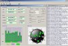
- Graphic GPS testing software is provided for free
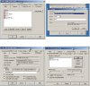
- Software for modifying baud rate is provided for free
- Interfaces: USB Mini-B and USB B interface, RS232 Female Interface, bluetooth
Testing it right now and it works well.


This will be replacing the legacy time based GPS (its been there about 7 years now).
BTW - The board pictured above and what I received look a bit different. There is only a small mini USB plug and no power plug on the one that I have.
I also notice that finding all of the satellites took less than 15 or so seconds versus the legacy GPS that takes a few minutes.
Will be putting into "production" shortly as the wife just asked me what it was and why its sitting there and what its purpose is?


I was working on this project at various "hubs" (they were around the world). It involved flight vectors based on a Unix application. (display was just a screen with a bunch of lines all over it). The server took data from multiple sources. What was kind of neat was that it was pretty dynamic with real time updates of the vectors. The geographical base and time came from an NTP GPS device the size of a Volkswagon Beetle. I wish I had a picture of it. It looked like a 1955 Chevy with a lot of chrome in its own dedicated room. Think it was called a Megadata beacon digital processor (it did more than GPS) for the Passur system (network-radar). In the late 1990's I wanted a similiar time base for HQ but the GPS that was utilized at the "hubs" was many thousands of dollars and I was on a "budget". Instead I decided to utilize some surplus little non destructive under any circumstance box which I purchased for about $50. It appeared to be built for a tank or some similiar style vehicle. A work peer and I climbed to the roof of HQ (there was access and it was only 4 stories). At the time on the roof were remnants of an old point to point microwave communications link. I remember numerous signs near the large parobolic microwave dishes warning you not to step in front of the dish. The microwave system had be decommissioned for many years; but still I envisioned myself being microwaved anyways if I walked in front of it. We climbed up some small little tower and installed a DIY GPS to PVC (glued) antenna using one of the old microwave antenna cables which went 4 stories and into the basement "server" facility. We utilized a small inline satellite amplifier and we could see 6 GPS satellites. This became an internal time base for DNS, all of the PCs, Servers, Routers and switches based at the location. I am guessing that its probably still being utilized today.
I've based my NTP time internally at home in a similiar fashion using a GPS, PC as base NTP and Tardis. A few years back mounted a GPS active antenna on the roof. Its basically a small automotive style antenna glued on a PVC pipe. I convert the cable to RG6 and use an inline amp before it goes to the reciever. Not perfectly accurate but very close the PC generates NTP to all of the clients on the network. It's a bit more accurate than the Internet but not as accurate as it could be.
Recently decided to update GPS. Found an experimental PC board. It came with antenna and USB cable for $37.99 (free shipping)
Features are:
- Low Power consumption
- Powered by USB port, no need to feed with DC power supply
- RF Receiver of Noise Figure is at 2.5 dB
- High Sensitivity -161 dBm( indoor)
- Seamless Outdoor/Indoor Operation
- Support standard NMEA-0183 V 3.01
- Graphic GPS testing software is provided for free
- Software for modifying baud rate is provided for free
- Interfaces: USB Mini-B and USB B interface, RS232 Female Interface, bluetooth
Testing it right now and it works well.
This will be replacing the legacy time based GPS (its been there about 7 years now).
BTW - The board pictured above and what I received look a bit different. There is only a small mini USB plug and no power plug on the one that I have.
I also notice that finding all of the satellites took less than 15 or so seconds versus the legacy GPS that takes a few minutes.
Will be putting into "production" shortly as the wife just asked me what it was and why its sitting there and what its purpose is?