This writeup discusses a sensor that can be used as part of another device to monitor the status of an AC power outlet. It uses a photocell to detect light and return a variable resistance. If this is plugged into an outlet, it can be used to monitor power outages (if the rest of the system is on a UPS) or the status of a wall switch. Plugged into the auxiliary outlet of a receiver, it can monitor the on/off status of the receiver. When there is no power applied to the device, the resistance will be quite high. When power is applied, it will be much lower.
=============================
WARNING: This thread discusses modifying a light which is designed to be plugged in to a normal household outlet. No electrical modifications are made to the light and the AC voltage is never exposed. However, it does involve adding an extra layer of material to the light which may increase its temperature during operation. I have tested this and not found any significant increase in temperature, but you should exercise appropriate caution.
=============================
In this thread on monitoring appliances, the discussion turned to monitoring an applicance with an indicator light (a washer in that particular case). The monitoring was done using an Ocelot, but the strategy could be used with other input devices.
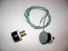
The main component required to monitor the light is a CdS (Cadmium Sulfide) photocell [1]. These are devices which have an electrical resistance which changes depending on the amount of light striking the photocell. Typically, the resistance in the dark is very high (can be several Mohms). In light, the resistance can be as low as 1 Kohm or less.
The photocells can be used as part of a voltage divider (in combination with another resistor) or may be usable directly across the terminals of some input device. For many devices, a high resistance is enough to act like an open switch. The photocells are very inexpensive, so they are easy to play with to see what works.
After that discussion, I decided to write up a project I've been thinking about for a while.
The device described here can be used as part of an input to a digital or analog I/O adapter connected to a computer or to something like an Ocelot.
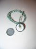
This component is built by mounting a photocell to an inexpensive night light. The particular night light is more of a marker light - it glows but does not light up the room. They are labeled as 1/3 Watt, but might actually consume less power.
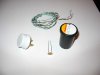
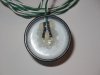
The picture shows a finished module along with an alternate (incomplete) version. The light is enclosed in the plastic can from a roll of 35mm film. The can prevents ambient light from affecting the resistance of the photocell. In reality, there is still some effect because light enters through the part of the night light which is still exposed. In testing, this effect was not enough to affect the results.
The can is an old Kodak can (back when they were black). Most film now comes in translucent white cans which will need to be painted to prevent light from going through the plastic.
If you don't have an old film can around, just go to a one-hour photo place and ask them for one. They should have plenty (unless everyone in the area has gone digital).
One module uses the top of the can - the cap can be removed to look at the interior. The other uses the bottom of the can. The bottom is a much tighter fit and is harder to work with.
I have had one of these night lights plugged in for several months (just as a light) to see if they get warm. They do not seem to get more than slightly warm to the touch. I have not tested them extensively with the film can over the light. It is possible that they will get warmer. I do not expect this to be a problem. But, please consider the possibility and treat them with appropriate care.
[1] There are other devices, such as phototransistors, which can also be used.
=============================
WARNING: This thread discusses modifying a light which is designed to be plugged in to a normal household outlet. No electrical modifications are made to the light and the AC voltage is never exposed. However, it does involve adding an extra layer of material to the light which may increase its temperature during operation. I have tested this and not found any significant increase in temperature, but you should exercise appropriate caution.
=============================
In this thread on monitoring appliances, the discussion turned to monitoring an applicance with an indicator light (a washer in that particular case). The monitoring was done using an Ocelot, but the strategy could be used with other input devices.
The main component required to monitor the light is a CdS (Cadmium Sulfide) photocell [1]. These are devices which have an electrical resistance which changes depending on the amount of light striking the photocell. Typically, the resistance in the dark is very high (can be several Mohms). In light, the resistance can be as low as 1 Kohm or less.
The photocells can be used as part of a voltage divider (in combination with another resistor) or may be usable directly across the terminals of some input device. For many devices, a high resistance is enough to act like an open switch. The photocells are very inexpensive, so they are easy to play with to see what works.
After that discussion, I decided to write up a project I've been thinking about for a while.
The device described here can be used as part of an input to a digital or analog I/O adapter connected to a computer or to something like an Ocelot.
This component is built by mounting a photocell to an inexpensive night light. The particular night light is more of a marker light - it glows but does not light up the room. They are labeled as 1/3 Watt, but might actually consume less power.
The picture shows a finished module along with an alternate (incomplete) version. The light is enclosed in the plastic can from a roll of 35mm film. The can prevents ambient light from affecting the resistance of the photocell. In reality, there is still some effect because light enters through the part of the night light which is still exposed. In testing, this effect was not enough to affect the results.
The can is an old Kodak can (back when they were black). Most film now comes in translucent white cans which will need to be painted to prevent light from going through the plastic.
If you don't have an old film can around, just go to a one-hour photo place and ask them for one. They should have plenty (unless everyone in the area has gone digital).
One module uses the top of the can - the cap can be removed to look at the interior. The other uses the bottom of the can. The bottom is a much tighter fit and is harder to work with.
I have had one of these night lights plugged in for several months (just as a light) to see if they get warm. They do not seem to get more than slightly warm to the touch. I have not tested them extensively with the film can over the light. It is possible that they will get warmer. I do not expect this to be a problem. But, please consider the possibility and treat them with appropriate care.
[1] There are other devices, such as phototransistors, which can also be used.

") ).
).")