beelzerob
Senior Member
So, having now installed almost all our ALC switches, I decided it'd probably be nice to share some of the lessons learned, in the form of a how-to guide for taking existing 3 and 4-way switches and converting them to an ALC switch.
But first, a couple disclaimers:
Ok then. I won't go into how you replace a normal 2-way switch, because it's pretty much trivial. Connect the neutral, ground, hot, and switched hot, and you're ready to go. What this "guide" will do, though, is show you how to make 3 and 4-way wiring into basically a 2-way switch, so you can then replace that switch with an ALC switch. Besides everything you'd normally use to make electrical connections, you'll also need a continuity tester.
This guide also assumes you've already run your cat5 wiring to the gang box, and that it is sitting on top, just behind the sheetrock.
So here goes. I'm going to describe changing a 4-way switch (4 locations to control the light) because encompassed within that is how to change a 3-way too (since a 4-way light circuit has a 3-way switch on both ends). If you only need to change a 3-way switch, then just skip the parts below that deal with the 4-way switch.
1) Before you even pull the switch cover off, take a sharp pencil and make a very light line at the top of the cover. That will help you to know how far up from the gang box you can cut to get access to the cat5 wire, without causing a gap between the plate cover and the wall. Don't make too sharp a line, or the paint and paper of the sheetrock will easily peel away when you cut below it.
2) Remove the cover, and pull out the 4-way switch so you can access it. I like to take pics of everything in case someday when we sell I need to reinsert the old switches. So, stick a piece of tape on the wall for reference. Also, if there are multiple of the same color of wires, I like to put little marks on one of them so I can see in the pic where that wire goes.
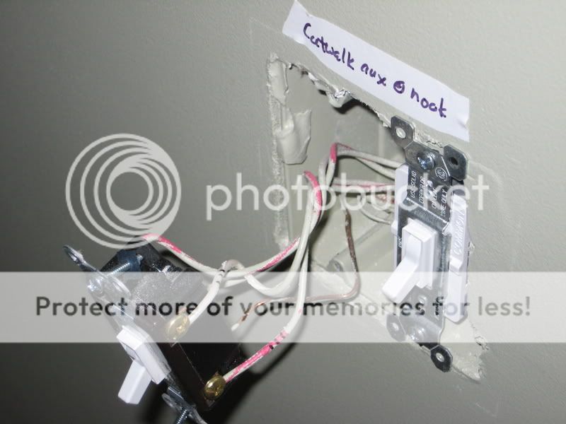
3) (Making sure the power is off....) Unscrew all the wires, but keep them in their same basic orientation to each other. What we're going to do is connect the wires with wirenuts in the exact same connection as they currently are. That way, there's no fear that you're somehow connecting a hot directly to neutral, or other possible bad ideas. We're simply making permanent the connection that was already there, so you KNOW it's safe.
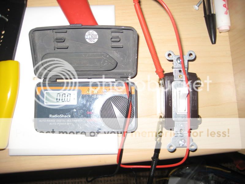
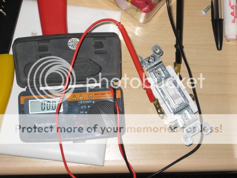
4) To do that, take the switch and use your continuity tester to see which screws were connected. Being a 4-way, that means the 4 wires were connected in pairs in some fashion.
Here we see that the left side wires were connected, and the right side wires were connected. So, go back to the switch box, and make those connections permanent. The remaining ground wire will be connected to your ALC aux switch.
Repeat this step for all other 4-way switches.
5) There should be 2 3-way switches left. One goes to the load, and one comes from the breaker box. Which is which? Dunno. Either way, decide which box you'll put your ALC switch in. Because of all the connections to be made, try to find a box it can go in that has a lot of room. In the other box (the one where an AUX switch will go), we're going to once again make the connection permanent that is currently there.
6) 3-way switches are different than 4-way and 2-way (duh!), but most notably because there are two "inputs", and 1 "output". That single output is called the common, and it should be very clearly labeled on the switch. It will either say COMMON in plain words, or at the very least be the different colored screw. If you're at all unsure which is the common on the switch, then use your continuity tester to see which screw makes a connection with both other screws, depending on switch position. For posterity and the possible eventual replacing of my ALC switches with the legacy switches, I label the common wire with a piece of tape marked "CMN".
7) So, pull out the 3-way, unattach the wires again keeping them in their respective locations to where they were, and then use the continuity tester to see which of the 2 screws is connected to the common wire.
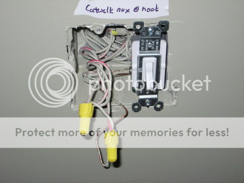
In this case, the lower left screw is connected to the common (upper right screw). So, go back to the switch box and make that connection permanent. There's one wire remaining once this is done. Once all is said and done, this wire will be dead...but it's NOT a good idea to leave a bare wire in any switch box. So, put a wire nut on it, cut it short and cover with electrical tape....whatever you need to do.
8) Now we go to the last 3-way switch. This is where your ALC switch will go. So remove the cover, and pull out the switch. This is also the point where we're going to turn the power back on briefly. Why? First, to test that your connections so far have been correct. If so, then you should be able to turn the load on and off from this one remaining switch. Second, we need to figure out which is the hot and which is the switched hot wires.
Use extreme caution at this part. You'll have an exposed switch pulled out of the wall with high voltage going through it. Lock up the kids if you have to, and always be aware of where any metal is as you move around it.
9) Turn on the power and go to the switch. First, test that the switch really does control the load. If it does, the congratulations, you've made a 2-way switch! If it doesn't, then something got messed up somewhere, and I suggest hiring a professional. Now, turn the load ON. If your handy current detector is sensitive enough, you should be able to tell which screws are "hot". If it's not sensitive enough, then you'll have to use a multimeter to see which ones have 110V on them.
You KNOW the common wire will be one of the two wires carrying current when the load is on...so find out which of the other two wires has a voltage on them. Once you've identified which two wires have 110V on them, turn the load OFF. Check those two wires again. The one that still has 110V on it is the HOT wire, the one that now has nothing on it is the SWITCHED HOT wire. Double check....the switched wire should become hot again when the load is turned on. Mark the wire so you remember which is hot, and which is switched hot (I used an alligator clip for the hot).
10) Turn off the power again.
11) Remove the wires from the switch and make the correct connections for the ALC switch....ground, neutral, hot and switched hot. For the neutral, you'll have to pull out the neutral wires that should be connected together within the box and add the ALC switch wire to the group. Don't forget to put a wirenut on the single loose wire from the 3-way.
12) Screw the switch into the box, turn on the power, and confirm that it works. Congratulations!
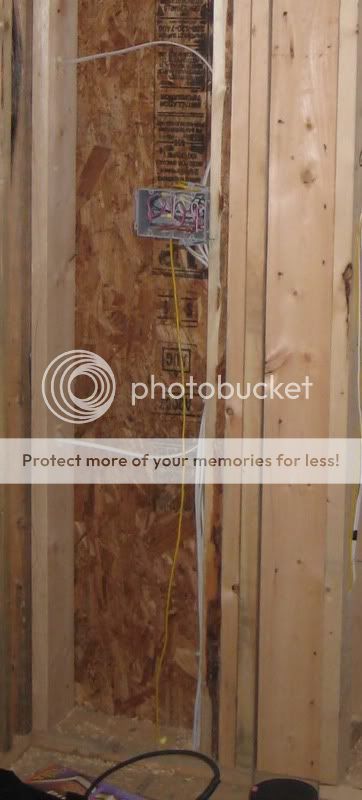
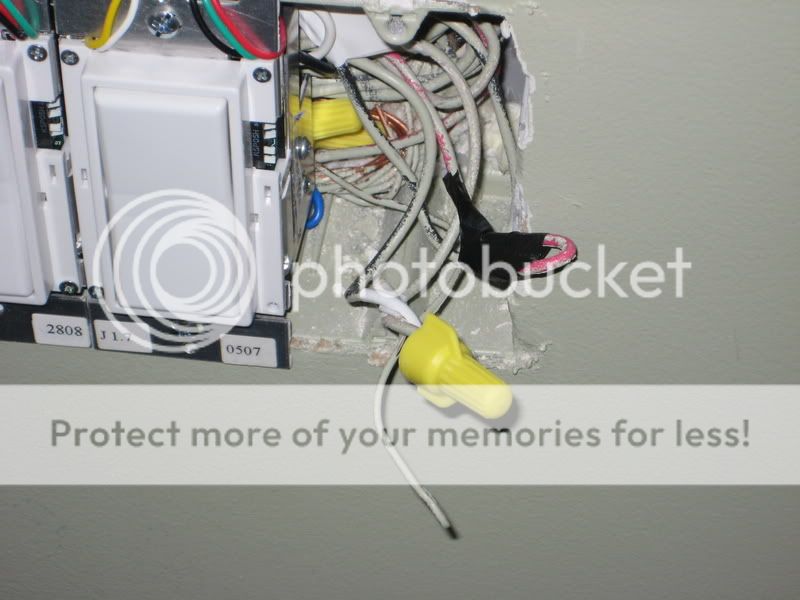
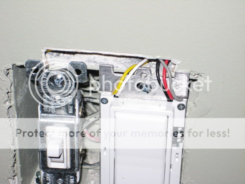
13) Using the mark you made before, cut out a section of sheetrock directly above the gang box. It doesn't have to span the entire box. Using some really expensive tool....or a bent coathanger like I did...fish in there and find the cat5 wire and pull it out. Assuming you have enough spare, cut off any part that gets mauled in the process.
14) Make the appropriate wire connections. I suggest writing down the color combination and keeping it as a handy reference guide and above all BE CONSISTENT. Write all this stuff down or you'll lose track when you get down to the wiring closet.
15) Stuff the wires back into the box, threading the wires through the gap in the switch so they stay out of the way.
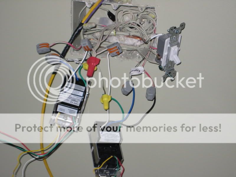
And you're done!
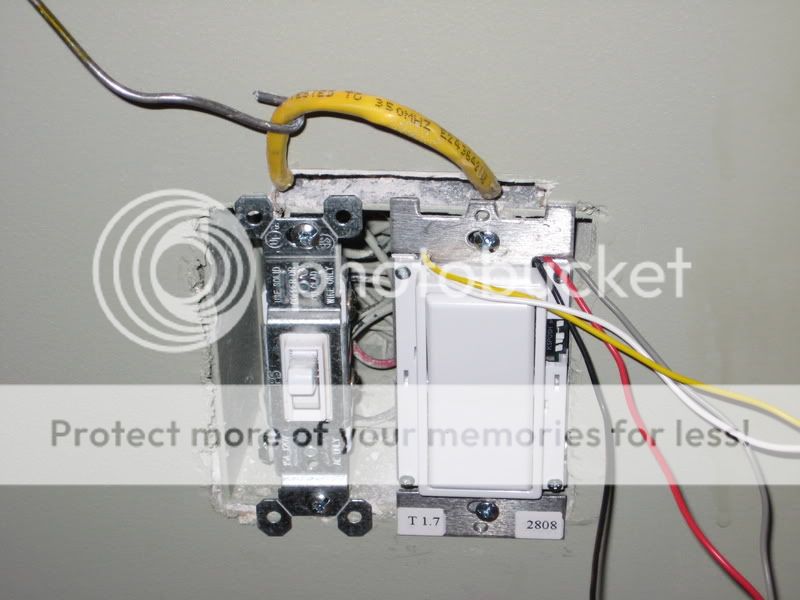
With enough practice, you too could have something that looks as safe and organized as this!
But first, a couple disclaimers:
- You're working with electricity, which is DANGEROUS. If you're not very comfortable doing that, then don't and hire a professional to do it.
[*]I am not an electrician, so the methods I suggest come with no guarantee that they're up to code, or even safe. They just simply worked for me. Use at your own risk.
[*]Always always triple check the power is off before you start doing anything. I highly recommend those little testers that beep or glow when near high voltage.
Ok then. I won't go into how you replace a normal 2-way switch, because it's pretty much trivial. Connect the neutral, ground, hot, and switched hot, and you're ready to go. What this "guide" will do, though, is show you how to make 3 and 4-way wiring into basically a 2-way switch, so you can then replace that switch with an ALC switch. Besides everything you'd normally use to make electrical connections, you'll also need a continuity tester.
This guide also assumes you've already run your cat5 wiring to the gang box, and that it is sitting on top, just behind the sheetrock.
So here goes. I'm going to describe changing a 4-way switch (4 locations to control the light) because encompassed within that is how to change a 3-way too (since a 4-way light circuit has a 3-way switch on both ends). If you only need to change a 3-way switch, then just skip the parts below that deal with the 4-way switch.
1) Before you even pull the switch cover off, take a sharp pencil and make a very light line at the top of the cover. That will help you to know how far up from the gang box you can cut to get access to the cat5 wire, without causing a gap between the plate cover and the wall. Don't make too sharp a line, or the paint and paper of the sheetrock will easily peel away when you cut below it.
2) Remove the cover, and pull out the 4-way switch so you can access it. I like to take pics of everything in case someday when we sell I need to reinsert the old switches. So, stick a piece of tape on the wall for reference. Also, if there are multiple of the same color of wires, I like to put little marks on one of them so I can see in the pic where that wire goes.
3) (Making sure the power is off....) Unscrew all the wires, but keep them in their same basic orientation to each other. What we're going to do is connect the wires with wirenuts in the exact same connection as they currently are. That way, there's no fear that you're somehow connecting a hot directly to neutral, or other possible bad ideas. We're simply making permanent the connection that was already there, so you KNOW it's safe.
4) To do that, take the switch and use your continuity tester to see which screws were connected. Being a 4-way, that means the 4 wires were connected in pairs in some fashion.
Here we see that the left side wires were connected, and the right side wires were connected. So, go back to the switch box, and make those connections permanent. The remaining ground wire will be connected to your ALC aux switch.
Repeat this step for all other 4-way switches.
5) There should be 2 3-way switches left. One goes to the load, and one comes from the breaker box. Which is which? Dunno. Either way, decide which box you'll put your ALC switch in. Because of all the connections to be made, try to find a box it can go in that has a lot of room. In the other box (the one where an AUX switch will go), we're going to once again make the connection permanent that is currently there.
6) 3-way switches are different than 4-way and 2-way (duh!), but most notably because there are two "inputs", and 1 "output". That single output is called the common, and it should be very clearly labeled on the switch. It will either say COMMON in plain words, or at the very least be the different colored screw. If you're at all unsure which is the common on the switch, then use your continuity tester to see which screw makes a connection with both other screws, depending on switch position. For posterity and the possible eventual replacing of my ALC switches with the legacy switches, I label the common wire with a piece of tape marked "CMN".
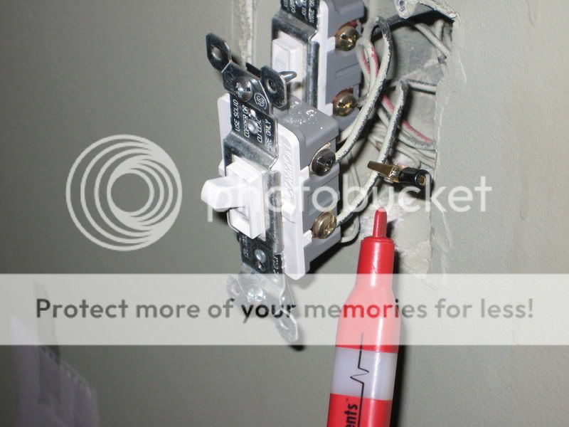
7) So, pull out the 3-way, unattach the wires again keeping them in their respective locations to where they were, and then use the continuity tester to see which of the 2 screws is connected to the common wire.
In this case, the lower left screw is connected to the common (upper right screw). So, go back to the switch box and make that connection permanent. There's one wire remaining once this is done. Once all is said and done, this wire will be dead...but it's NOT a good idea to leave a bare wire in any switch box. So, put a wire nut on it, cut it short and cover with electrical tape....whatever you need to do.
8) Now we go to the last 3-way switch. This is where your ALC switch will go. So remove the cover, and pull out the switch. This is also the point where we're going to turn the power back on briefly. Why? First, to test that your connections so far have been correct. If so, then you should be able to turn the load on and off from this one remaining switch. Second, we need to figure out which is the hot and which is the switched hot wires.
Use extreme caution at this part. You'll have an exposed switch pulled out of the wall with high voltage going through it. Lock up the kids if you have to, and always be aware of where any metal is as you move around it.
9) Turn on the power and go to the switch. First, test that the switch really does control the load. If it does, the congratulations, you've made a 2-way switch! If it doesn't, then something got messed up somewhere, and I suggest hiring a professional. Now, turn the load ON. If your handy current detector is sensitive enough, you should be able to tell which screws are "hot". If it's not sensitive enough, then you'll have to use a multimeter to see which ones have 110V on them.
You KNOW the common wire will be one of the two wires carrying current when the load is on...so find out which of the other two wires has a voltage on them. Once you've identified which two wires have 110V on them, turn the load OFF. Check those two wires again. The one that still has 110V on it is the HOT wire, the one that now has nothing on it is the SWITCHED HOT wire. Double check....the switched wire should become hot again when the load is turned on. Mark the wire so you remember which is hot, and which is switched hot (I used an alligator clip for the hot).
10) Turn off the power again.
11) Remove the wires from the switch and make the correct connections for the ALC switch....ground, neutral, hot and switched hot. For the neutral, you'll have to pull out the neutral wires that should be connected together within the box and add the ALC switch wire to the group. Don't forget to put a wirenut on the single loose wire from the 3-way.
12) Screw the switch into the box, turn on the power, and confirm that it works. Congratulations!
13) Using the mark you made before, cut out a section of sheetrock directly above the gang box. It doesn't have to span the entire box. Using some really expensive tool....or a bent coathanger like I did...fish in there and find the cat5 wire and pull it out. Assuming you have enough spare, cut off any part that gets mauled in the process.
14) Make the appropriate wire connections. I suggest writing down the color combination and keeping it as a handy reference guide and above all BE CONSISTENT. Write all this stuff down or you'll lose track when you get down to the wiring closet.
15) Stuff the wires back into the box, threading the wires through the gap in the switch so they stay out of the way.
And you're done!
With enough practice, you too could have something that looks as safe and organized as this!