BraveSirRobbin
Moderator
[How-To] Measure Gas Water Heater Energy Usage
by Michael McSharry
Fellow Cocooner Michael McSharry has kindly submitted the following [How-To] to CocoonTech.com for publication.
CocoonTech would like to thank Michael for this informative article as it is a really unique and ingenious solution for measuring a gas water heater's gas utilization.
Thanks again for this great [How-To] Michael!")
---------------------------------------------------------------------------------------------------------------------
Measurement of Gas Water Heater Gas Utilization
Michael McSharry
September 22, 2006
Introduction
In the quest to measure energy use, the gas water heater presents a problem because there is nothing electrical or mechanical that can be measured to know when it consuming gas. Ideally a flow meter to track LP or natural gas use would be the desired choice since it directly measures the utilization. I have not stumbled over any LP flow meters, much less meters that have an automation interface.
Water Temperature Measurement
The first approach to measure the water heater operation was with a temperature sensor attached to the copper hot water outlet. A hose clamp was used to attach the sensor to the pipe for a positive transfer of heat from the pipe to the sensor. The hot water recalculates so as the tank temperature goes down so does the outlet temperature. When this is measured it shows the pattern of decay and then temperature rise with about 4 cycles per day. When looking at the rise time it showed about 30 minutes from when the water temperature started to rise to when it peaked. This is a reasonable approximation. This technique is feasible because of the recirc pump on the hot water brings the heated water to a place where it can be easily measured. It is not ideal because of the uncertainty of how long the gas is on before the temperature rises.

Figure 1 Temperature of Hot Water Outlet (24 hours)

Figure 2 Temperature of Hot Water Outlet (6 Hours)
Combustion Chamber Temperature Measurement
To remove the uncertainty associated with the warm-up time a temperature sensor is placed in the combustion chamber at a location where it can measure temperature changes, but not so deeply embedded in the chamber that it destroys the sensor. The chart below shows a much steeper temperature slope so the desired effect has been achieved. It also does not depend upon the recirc pump so it can be used with any gas water heater.
The temperature rise is good information, but it needs to be converted into binary ON/OFF of the gas valve. A trigger temperature needs to be selected so that ambient temperature will always below it and a delta can be measured when the water heater is heating. The first of the charts below used a relatively high threshold and resulted in ON time pulses (blue line) that were short and not reflective of the time that the gas was actually ON. The second chart used more refined trigger points that appear to come closer to the desired measurement.
Even with this there is still uncertainty as to when the gas actually turned off. The peak at the turn-off time was not a sharp peak, but the slope changed as if the amount of gas to the chamber was reduced. I suspect that the valve is not that smart and this is just an artifact of measurement.
The software used to collect the temperature and synthesize an ON/OFF based upon the temperature is xapmcs1Wire. It implements a single trigger point with a 20% hysteresis band. This algorithm assumes the rise and decay slopes are equivalent. From the charts it can be seen that this is not exactly the case, but they are close. A more precise ON/OFF could be generated if separate user-inputs are made available for ON and OFF criteria.

Figure 3 Temperature of Combustion Chamber

Figure 4 Temperature of Combustion Chamber with Trigger Adjustment
Flame Presence Measurement
Measurement of temperature carries with it the uncertainty of the thermal delays. The use of chamber temperature rather than water temperature reduces the uncertainty, but it is still present.
To make the measurement better a technique of measuring light rather than temperature is used. When the water heater is not heating there is a pilot light that emits a small amount of light. When it is heating then the flame is much more robust and greater light is emitted.
The initial attempt to discriminate the pilot vs. full flame was done using a photodiode interfaced with 1-wire and supplied by hobby-boards.com as a solar sensor. It turns out that the range of visible light that could be measured was outside the range provided by the water heater combustion chamber. At the low light level end of the circuit there was very little margin above the noise level of the photodiode so adjustments to the circuit would not have much benefit.
The desired discrimination between pilot and full flame is achievable with a photoresistor and conveniently with the photoresistor that is provided with the X10 hawkeye dawn/dusk sensor. To modify the hawkeye the photoresistor is removed and then reattached at the end of a length of wire that will allow penetration into the water heater combustion chamber. The photosensor is the device on the hawkeye near the center of the circuit that is attached with a glob of clear silicon rubber. The circuit card is labeled CDS at this location. This device can be unsoldered as I did or it can be cut. If it is cut then leave enough of the leads so it can be attached at the end of the wire.
In my case I drilled a 3/16 hole in the back of the hawkeye at the exact position of the photoresistor and used cat5 trough this hole and soldered two of the wires to the circuit board holes where the photoresistor was removed. It is also possible to route the wires to the side of the hawkeye.
At the other end of the cat5 the photoresistor is soldered to the same wires that were attached to the circuit card. Use heat shrink or similar to assure the two leads are electrically isolated. I attached a larger heat shrink over the entire photoresistor and cat5 cable for mechanical strength. After the heat shrink tube is heated over the photoresistor then trim the end of heat shrink tube flush with the face of the photoresistor so it does not obstruct the ability of light to enter the sensor. The assembly is shown in the figure below.

(Click on Picture for Full Sized Image)
Figure 5 Hawkeye Mod to Extend Photoresistor
The initial test of this unit showed it to also not have the desired range of light level detection. The full flame was not bright enough to make the hawkeye think is was no longer after dusk. When looking at the brightness of the flame vs. the light level from a room’s lightbulb it did not seem reasonable. Apparently the spectrum for the flame is not the same as a lightbulb.
To deal with this a resistor is added to bias the trigger point. This resistor can be added inside the case of the hawkeye. In my case I attached it external between the two wires of the cat5 cable. In my case 150K ohm resistor provided the desired result. It was not necessary to have the photoresistor installed in the water heater combustion chamber when the resistor is being selected. Select the resistor by covering the photoresistor so it sees darkness then select a resistor in the neighborhood of 150K where the hawkeye continue to report darkness. As the resistor value is lowered the hawkeye will tend to report OFF to indicate it is light rather than dusk. If the resistor value is increased then it will take more light to trigger it. The use of a variable resistor with the desired 200K range will make the adjustment easiest.

(Click on Picture for Full Sized Image)
Figure 6 Light Sensitivity Circuit Modification
The install of the cable with the photosensor protected with green heat shrink is shown the Figure 7. Access to the chamber is achieved via the same route that is used to provide the gas to the chamber as well as the thermocouple. A clear plastic shroud already existed to protect the plumbing from the access panel which was used to help contain the cat5 cable. The original temperature sensor was also retained so both measurements are now being made.

(Click on Picture for Full Sized Image)
Figure 7 Sensor Installed in Combustion Chamber
When the results of the temperature measurement (Pink and Blue) and flame measurement (Green) are compared it can be seen that the durations estimated with temperature and measured with flame are about the same. They are skewed in time which is expected and is the delay associated with heating of the combustion chamber.

Figure 8 Measurement of Water Heater Flame vs. Temperature
About Michael McSharry
I’ve been designing flight control systems for space and military applications since the 1970’s and became interested in home automation about five years ago. I’ve poked around with various HA technologies primarily as a learning experiece. My current focus is the R&D associated with distributed computing and the management of redundancy to maximize functional availability within this architecture. In the long term I expect IP-based connectivity to increase amongst devices within the household. An area of opportunity and challenge is a decentralized management of these devices to achieve a natural convergence of functionality.
by Michael McSharry
Fellow Cocooner Michael McSharry has kindly submitted the following [How-To] to CocoonTech.com for publication.
CocoonTech would like to thank Michael for this informative article as it is a really unique and ingenious solution for measuring a gas water heater's gas utilization.
Thanks again for this great [How-To] Michael!
---------------------------------------------------------------------------------------------------------------------
Measurement of Gas Water Heater Gas Utilization
Michael McSharry
September 22, 2006
Introduction
In the quest to measure energy use, the gas water heater presents a problem because there is nothing electrical or mechanical that can be measured to know when it consuming gas. Ideally a flow meter to track LP or natural gas use would be the desired choice since it directly measures the utilization. I have not stumbled over any LP flow meters, much less meters that have an automation interface.
Water Temperature Measurement
The first approach to measure the water heater operation was with a temperature sensor attached to the copper hot water outlet. A hose clamp was used to attach the sensor to the pipe for a positive transfer of heat from the pipe to the sensor. The hot water recalculates so as the tank temperature goes down so does the outlet temperature. When this is measured it shows the pattern of decay and then temperature rise with about 4 cycles per day. When looking at the rise time it showed about 30 minutes from when the water temperature started to rise to when it peaked. This is a reasonable approximation. This technique is feasible because of the recirc pump on the hot water brings the heated water to a place where it can be easily measured. It is not ideal because of the uncertainty of how long the gas is on before the temperature rises.
Figure 1 Temperature of Hot Water Outlet (24 hours)
Figure 2 Temperature of Hot Water Outlet (6 Hours)
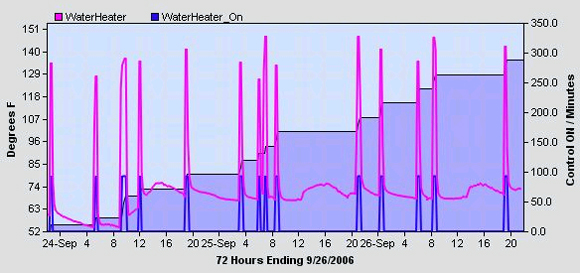
Combustion Chamber Temperature Measurement
To remove the uncertainty associated with the warm-up time a temperature sensor is placed in the combustion chamber at a location where it can measure temperature changes, but not so deeply embedded in the chamber that it destroys the sensor. The chart below shows a much steeper temperature slope so the desired effect has been achieved. It also does not depend upon the recirc pump so it can be used with any gas water heater.
The temperature rise is good information, but it needs to be converted into binary ON/OFF of the gas valve. A trigger temperature needs to be selected so that ambient temperature will always below it and a delta can be measured when the water heater is heating. The first of the charts below used a relatively high threshold and resulted in ON time pulses (blue line) that were short and not reflective of the time that the gas was actually ON. The second chart used more refined trigger points that appear to come closer to the desired measurement.
Even with this there is still uncertainty as to when the gas actually turned off. The peak at the turn-off time was not a sharp peak, but the slope changed as if the amount of gas to the chamber was reduced. I suspect that the valve is not that smart and this is just an artifact of measurement.
The software used to collect the temperature and synthesize an ON/OFF based upon the temperature is xapmcs1Wire. It implements a single trigger point with a 20% hysteresis band. This algorithm assumes the rise and decay slopes are equivalent. From the charts it can be seen that this is not exactly the case, but they are close. A more precise ON/OFF could be generated if separate user-inputs are made available for ON and OFF criteria.
Figure 3 Temperature of Combustion Chamber
Figure 4 Temperature of Combustion Chamber with Trigger Adjustment
Flame Presence Measurement
Measurement of temperature carries with it the uncertainty of the thermal delays. The use of chamber temperature rather than water temperature reduces the uncertainty, but it is still present.
To make the measurement better a technique of measuring light rather than temperature is used. When the water heater is not heating there is a pilot light that emits a small amount of light. When it is heating then the flame is much more robust and greater light is emitted.
The initial attempt to discriminate the pilot vs. full flame was done using a photodiode interfaced with 1-wire and supplied by hobby-boards.com as a solar sensor. It turns out that the range of visible light that could be measured was outside the range provided by the water heater combustion chamber. At the low light level end of the circuit there was very little margin above the noise level of the photodiode so adjustments to the circuit would not have much benefit.
The desired discrimination between pilot and full flame is achievable with a photoresistor and conveniently with the photoresistor that is provided with the X10 hawkeye dawn/dusk sensor. To modify the hawkeye the photoresistor is removed and then reattached at the end of a length of wire that will allow penetration into the water heater combustion chamber. The photosensor is the device on the hawkeye near the center of the circuit that is attached with a glob of clear silicon rubber. The circuit card is labeled CDS at this location. This device can be unsoldered as I did or it can be cut. If it is cut then leave enough of the leads so it can be attached at the end of the wire.
In my case I drilled a 3/16 hole in the back of the hawkeye at the exact position of the photoresistor and used cat5 trough this hole and soldered two of the wires to the circuit board holes where the photoresistor was removed. It is also possible to route the wires to the side of the hawkeye.
At the other end of the cat5 the photoresistor is soldered to the same wires that were attached to the circuit card. Use heat shrink or similar to assure the two leads are electrically isolated. I attached a larger heat shrink over the entire photoresistor and cat5 cable for mechanical strength. After the heat shrink tube is heated over the photoresistor then trim the end of heat shrink tube flush with the face of the photoresistor so it does not obstruct the ability of light to enter the sensor. The assembly is shown in the figure below.

(Click on Picture for Full Sized Image)
Figure 5 Hawkeye Mod to Extend Photoresistor
The initial test of this unit showed it to also not have the desired range of light level detection. The full flame was not bright enough to make the hawkeye think is was no longer after dusk. When looking at the brightness of the flame vs. the light level from a room’s lightbulb it did not seem reasonable. Apparently the spectrum for the flame is not the same as a lightbulb.
To deal with this a resistor is added to bias the trigger point. This resistor can be added inside the case of the hawkeye. In my case I attached it external between the two wires of the cat5 cable. In my case 150K ohm resistor provided the desired result. It was not necessary to have the photoresistor installed in the water heater combustion chamber when the resistor is being selected. Select the resistor by covering the photoresistor so it sees darkness then select a resistor in the neighborhood of 150K where the hawkeye continue to report darkness. As the resistor value is lowered the hawkeye will tend to report OFF to indicate it is light rather than dusk. If the resistor value is increased then it will take more light to trigger it. The use of a variable resistor with the desired 200K range will make the adjustment easiest.

(Click on Picture for Full Sized Image)
Figure 6 Light Sensitivity Circuit Modification
The install of the cable with the photosensor protected with green heat shrink is shown the Figure 7. Access to the chamber is achieved via the same route that is used to provide the gas to the chamber as well as the thermocouple. A clear plastic shroud already existed to protect the plumbing from the access panel which was used to help contain the cat5 cable. The original temperature sensor was also retained so both measurements are now being made.

(Click on Picture for Full Sized Image)
Figure 7 Sensor Installed in Combustion Chamber
When the results of the temperature measurement (Pink and Blue) and flame measurement (Green) are compared it can be seen that the durations estimated with temperature and measured with flame are about the same. They are skewed in time which is expected and is the delay associated with heating of the combustion chamber.
Figure 8 Measurement of Water Heater Flame vs. Temperature
About Michael McSharry
I’ve been designing flight control systems for space and military applications since the 1970’s and became interested in home automation about five years ago. I’ve poked around with various HA technologies primarily as a learning experiece. My current focus is the R&D associated with distributed computing and the management of redundancy to maximize functional availability within this architecture. In the long term I expect IP-based connectivity to increase amongst devices within the household. An area of opportunity and challenge is a decentralized management of these devices to achieve a natural convergence of functionality.