Hello everyone,
Purchased the Hobby Board Anemometer Controller with the InSpeed Wind Sensors about four years ago.
Connected it to my 1-wire 'Web Energy Logger' (WEL). Never got around to calibrate neither the anemometer or the wind vane.
Found that I had my sensor swapped in the logger. Once corrected was able to get the anemometer running and calibrated.
However, my wind vane was always showing 2 degrees wind direction no matter which direction was pointing. This is a Hall-effect sensor which outputs the signal to the DS2438 - Vad.
Contact Inspeed.com Lorenzo emailed back saying the PCB in bottom of sensor was probably bad and would cost $20 to replace.
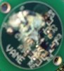
Remove PCB from vane (two small screws under sensor) and found heap of corrosion onto of PCB. Clean corrosion of with IPA and old toothbrush. Still no go.
Order new PCB from Lorenzo and reinstalled it back into bottom of sensor. With input of 4.93 Vdc hook my Fluke to signal output. Tested by revolving the vane around clockwise: Voltage start at 0.243 Vdc and increases to 4.69 Vdc where it drops back to 0.243 Vdc. So wind vane is working within spec.
Hook vane signal wire to HB board's A/D connector and connect HB board to OneViewer view the Vad voltage reading. Now revolving the vane around the voltage ranged between 0.234 and 4.0 Vdc. Verified the DS2438 Vad reading with my Fluke. Readings between DS2438 and Fluke meter were the same. This would not be so bad but when revolving the vane clockwise in a 360 degree rotation: 0.234v -> increases to 4.0v then begins to decrease until it is about 3.6?v -> then drops back 0.234v
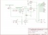
Found below a copy of Hobby Board Anemometer Controller schematic...
At Url: gharper.co.za/Interests/One-Wire/GHowSAW/GHowSAW_Setup.asp
Trying figure out why having a grounded resistor 'R1' 10K connecting to the Wind vane output (A/D) to DS2438 Vad pinout. Note: resistor 'R2' 2K is used when the 'ADS' anemometer/vane is used.
InSpeed suggesting replacing R1 and R2 resistors with 50K value.
Any suggestions?
Bob G.
Purchased the Hobby Board Anemometer Controller with the InSpeed Wind Sensors about four years ago.
Connected it to my 1-wire 'Web Energy Logger' (WEL). Never got around to calibrate neither the anemometer or the wind vane.
Found that I had my sensor swapped in the logger. Once corrected was able to get the anemometer running and calibrated.
However, my wind vane was always showing 2 degrees wind direction no matter which direction was pointing. This is a Hall-effect sensor which outputs the signal to the DS2438 - Vad.
Contact Inspeed.com Lorenzo emailed back saying the PCB in bottom of sensor was probably bad and would cost $20 to replace.
Remove PCB from vane (two small screws under sensor) and found heap of corrosion onto of PCB. Clean corrosion of with IPA and old toothbrush. Still no go.
Order new PCB from Lorenzo and reinstalled it back into bottom of sensor. With input of 4.93 Vdc hook my Fluke to signal output. Tested by revolving the vane around clockwise: Voltage start at 0.243 Vdc and increases to 4.69 Vdc where it drops back to 0.243 Vdc. So wind vane is working within spec.
Hook vane signal wire to HB board's A/D connector and connect HB board to OneViewer view the Vad voltage reading. Now revolving the vane around the voltage ranged between 0.234 and 4.0 Vdc. Verified the DS2438 Vad reading with my Fluke. Readings between DS2438 and Fluke meter were the same. This would not be so bad but when revolving the vane clockwise in a 360 degree rotation: 0.234v -> increases to 4.0v then begins to decrease until it is about 3.6?v -> then drops back 0.234v
Found below a copy of Hobby Board Anemometer Controller schematic...
At Url: gharper.co.za/Interests/One-Wire/GHowSAW/GHowSAW_Setup.asp
Trying figure out why having a grounded resistor 'R1' 10K connecting to the Wind vane output (A/D) to DS2438 Vad pinout. Note: resistor 'R2' 2K is used when the 'ADS' anemometer/vane is used.
InSpeed suggesting replacing R1 and R2 resistors with 50K value.
Any suggestions?
Bob G.