UPB wiring - bathroom exhaust fan

michelkenny

Active Member
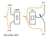
I’m in the process of wiring my house with SA UPB switches. I have most of my lights done without any problems. Now I am trying to get my bathroom exhaust fans automated but I am unsure how to wire the switches. See attached for a diagram. The fan switch activates my house’s central exhaust system. The switch is wired in such a way that when the switch is turned on, it connects all the black wires to the white wires. I am unsure how to wire in a UPB switch, possibly making use of any wires from the light if needed.

Any assistance would be greatly appreciated.

I should add that I've already tried to wire the black wire from the switch to the black wires for the fan, as well as the white and brown (load) wires to the white wires from the switch. The SA UPB switch turns on and is able to activate the fan, but when it activates the fan it reboots.
 

Attachments

  • bathroom.png
    bathroom.png
    28.8 KB · Views: 4
Unless you have a strange wiring situation, it should be:

All white wires (neutral) in the switchbox wired together with the UPB white.
The black (incoming hot) wired to the UPB black wire.
The black (outgoing load) wired to the UPB brown wire.
The bare copper (ground) to the UPB bare copper.
Any other UPB switch wires (red/white or brown/white) capped.

In Upstart, disable dimming on the switch, so it acts as on/off only.

Your diagram above shows the neutral switched to the hot.
Is that what it looks like inside the switchbox?
You may have to look at how the central system is wired at the fan control box.
Those whites in the switchbox may not really be neutrals, they may be hot travellers.
There may be a dedicated neutral feeding the fan control and the switch(es) is(are) merely providing the hot connection(s) to the relay.

I Googled this sytems - your wiring may be similar.
http://www.breathepureair.com/pdf/thermastor/BPAQuiet-Vent.pdf

If that is the case then I expect those whites at the fan switch are not neutrals, they are probably the travelers back to the conrol unit - blue in the wiring diagram on page 8.

I'd check the wires with a multimeter but I think my guess is close.
My guess, you should have 120VAC from the fan blacks to the light white (be careful with 120VAC if you don't know what you are doing - don't meter a hot circuit)!
You should have 0VAC from the fan blacks to the fan whites - but when connected together, the fan runs.
You should have 0VAC from the fan whites to the light white.
If you have a circuit tracer/tone generator, you could hook it up to the fan control unit wiring to determine which of the fan wires is hot and which is the relay traveller.

If those whites are not neutrals, and it is a two gang box and there is another white neutral inside, you could try this.

Wire the UPB white to the neutral from the light circuit (the switch needs a neutral for comms and to run properly, but the fan system only needs the hot signal).
Wire the UPB black to the group of hots (my guess is the fan blacks).
Wire the UPB brown to the group of loads (my guess is the fan whites).
 
Thanks for your reply. I believe you are right, see attached for the wiring page from my fan's manual. We do not have a speed control but I imagine that the switches are wired in the same way, which is what you described.
 

Attachments

  • fan.png
    fan.png
    37.7 KB · Views: 14
My guess, you should have 120VAC from the fan blacks to the light white (be careful with 120VAC if you don't know what you are doing - don't meter a hot circuit)!
You should have 0VAC from the fan blacks to the fan whites - but when connected together, the fan runs.
You should have 0VAC from the fan whites to the light white.
If you have a circuit tracer/tone generator, you could hook it up to the fan control unit wiring to determine which of the fan wires is hot and which is the relay traveller.

If those whites are not neutrals, and it is a two gang box and there is another white neutral inside, you could try this.

Wire the UPB white to the neutral from the light circuit (the switch needs a neutral for comms and to run properly, but the fan system only needs the hot signal).
Wire the UPB black to the group of hots (my guess is the fan blacks).
Wire the UPB brown to the group of loads (my guess is the fan whites).

Just to let you know that you were right. I took my multimeter and was able to find out that the fan whites were actually the hots, and the fan blacks the load. Wired the switch as you described (swapping fan black for fan white) and it works fine.

Thanks a lot for the help!
 
Just to let you know that you were right. I took my multimeter and was able to find out that the fan whites were actually the hots, and the fan blacks the load. Wired the switch as you described (swapping fan black for fan white) and it works fine.

Thanks a lot for the help!

Glad I could help - I love figuring out these electrical wiring puzzles. :D


The one potential for problem here is the neutral from the light circuit may not be on the same circuit as the fan. But since you are just borrowing the neutral, I don't think it will be a huge deal. All the neutrals are connected to the same bus bar in the panel anyway.
I'm beyond my paygrade if we start discussing AFI/GFCI circuits.
 
Watch out for overload on the UPB switches. They will fry before a 15A circuit breaker trips. I had someone plug a heater into a UPB controlled wall outlet and the switch started cooking and it failed in the closed position...would not turn off at the switch. Had to unplug the heater. Just smoked the switch but would have been a fire if I had not been there to unplug the heater.
 
Watch out for overload on the UPB switches. They will fry before a 15A circuit breaker trips. I had someone plug a heater into a UPB controlled wall outlet and the switch started cooking and it failed in the closed position...would not turn off at the switch. Had to unplug the heater. Just smoked the switch but would have been a fire if I had not been there to unplug the heater.

Correct me if I am wrong, but isn't a heater a completely different scenario than a fan since a heater would be taking up many more amps than a fan?
 
Back
Top