Zone & EOL connections

richard

Member
Using M1G and a 16 zone expander I have a problem that can not resolve;

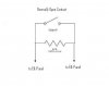
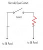
From the diagram attached using a NO magnet sensor at a door with EOL in the circuit . Does not seem to work as expected. Expander shows up at zones 17 - 32.

I select " 0 " type in elkRP for the zone wiring type and wired NO sensor and 22K resistor as shown.

* When I place magnet at sensor I do not get "closed loop" or referred to as shorted.
what am I do wrong ?

On the zone expander is there anything I can trouble shoot ?

Using the EOL to detect a "nail through the wire when circuit is open" as an additional safety measure. ;)

Could problem be zone expander settings, elkrp sees the expander, it is terminated and only device on this buss.

Thanks in advance.
 

Attachments

  • no_with_eol2.JPG
    no_with_eol2.JPG
    10 KB · Views: 31
You need to put the resistor in series and not parallel. Make sure the resistor is as close to the sensor end as possible. Also when the magnet is near the sensor (door/window in closed position), the contacts should be "closed".
 

Attachments

  • correct.jpg
    correct.jpg
    9.1 KB · Views: 22
Actually, I think Richard is correct. With an open loop circuit (the loop is open when the door is secure) then the resister goes in parallel with the contact. With a closed loop circuit (the loop is closed when the door is secure) then the resisiter goes in series.

HTH,
Brett
 
You need to put the resistor in series and not parallel. Make sure the resistor is as close to the sensor end as possible. Also when the magnet is near the sensor (door/window in closed position), the contacts should be "closed".

Can you explain why series is more secure than parallel. Resulting in monitored wiring 24 hours?

(beside the fact my wiring did not work?

It was drawn as my example in the KP keypad manual so I further do not understand??

This does not make sense, please allow my attempt to clarify, if the zone is wired per my drawing- the zone would see
a 22K load when (Normally Open) is open and a "short when closed" by the door closure... is that most secure, and monitored wiring configuration?

also from your wiring info I would still use "wiring type 0 in the elkrp setup"

Thanks again....
 
On second thought, I just reread Richard's post and it looks like BSR is correct. It sounds like richard does have a closed loop circuit, and in that case, the resistor should be in series.

Brett
 
Hmm, sorry, I was not looking at the posting correctly.

I am not sure why it isn't working, my Elk isn't connected to a computer right now, so I can't simulate your scenario.

If I get it back in operation, I will try this out.
 
Can you explain why series is more secure than parallel. Resulting in monitored wiring 24 hours?

It works like this. With a closed loop circuit (the circuit is closed when the door is secure) and with no resistor, then the circuit is essentially shorted whenever the door is closed. Theoretically someone could short the wires between the panel and the door, or as you said, you could drive a nail through the wire and short them and the panel would simply think the door was closed even when it was opened.

When you add a resistor in series at the sensor (it does no good to add it at the panel) then when the door is closed the elk will see resistance on the circuit. If someone shorted the wire or your drove a nail into the wire and shorted it, then there would be no resistance and the elk would know there is a problem.

In either case, when the circuit is open it would go into alarm state. If someone cut the wire or if you drove a nail into it and broke the wire, then it would get stuck in alarm state and you would still know there was a problem

For an open loop (the circuit is open when the door is secure) it's just the opposite. With no resistor then the circuit is open when the door is closed. If someone were to cut the wire or you drove a nail into it and cut it then the panel would think the door was closed no matter what.

With a resistor wired in parallel at the sensor (again, it does no good at the panel) then when the door is closed the panel will see resisitance on the circuit. Again, if the wire got cut between the panel and the sensor then the resistance would go away and the panel would know there was a problem.

And in either case for an open loop, when the circuit is closed (the door is closed or the wire gets shorted) then it goes into alarm and you would be aware of a problem.

HTH
Brett
 
This does not make sense, please allow my attempt to clarify, if the zone is wired per my drawing- the zone would see
a 22K load when (Normally Open) is open and a "short when closed" by the door closure... is that most secure, and monitored wiring configuration?

No, that's not correct. See my description above. You want the wire to be monitored with the resistor when it's in the secure state (with the door closed)... it doesn't matter if it's monitored when the door is not secure.

For what you just described the resistor should be in series for a secure and monitored wiring configuration. Both closed loop and open loop with resistors are equally secure, however, I believe that closed loop is more common.

Brett
 
Can you explain why series is more secure than parallel. Resulting in monitored wiring 24 hours?

It works like this. With a closed loop circuit (the circuit is closed when the door is secure) and with no resistor, then the circuit is essentially shorted whenever the door is closed. Theoretically someone could short the wires between the panel and the door, or as you said, you could drive a nail through the wire and short them and the panel would simply think the door was closed even when it was opened.

When you add a resistor in series at the sensor (it does no good to add it at the panel) then when the door is closed the elk will see resistance on the circuit. If someone shorted the wire or your drove a nail into the wire and shorted it, then there would be no resistance and the elk would know there is a problem.

In either case, when the circuit is open it would go into alarm state. If someone cut the wire or if you drove a nail into it and broke the wire, then it would get stuck in alarm state and you would still know there was a problem

Brett

So as I digest this ... the panel either sees a 22K ohm resistance on the circuit (monitored wiring value) or an open.

1
so if a nail was driven through wiring it might show a direct short (not the 22K value) indicating a problem or an open also indicating a problem.

2
the wiring in this config is not supervised when it is * cut or * door open ( and there is not a way to do this on a NO sensor)

Is there a way to get supervised wiring (what hardware and configuration)all the time in both open and closed door sensors? I thought that was what I would end up with but I see you explaination is supervised only on a closed sensor (22K in circuit).

wow I am on a ledge her and barely understanding the wiring choices. ;)

Interested to understand these concepts.

Thanks again.
 
Also, a couple of questions.

Do you really have a 22K resistor or is it 2.2K? Also, do you have contacts that are closed or opened when the magnet is near it?

I believe you are looking at the diagram below that I took from the installation guide.

Also, what are the voltages that are displayed on the status diagnostic (forget where this is in the RP program, but you can look at real time voltage the zone is seeing) when open and closed?
 

Attachments

  • elkzone.jpg
    elkzone.jpg
    135.7 KB · Views: 35
So as I digest this ... the panel either sees a 22K ohm resistance on the circuit (monitored wiring value) or an open.

1
so if a nail was driven through wiring it might show a direct short (not the 22K value) indicating a problem or an open also indicating a problem.

2
the wiring in this config is not supervised when it is * cut or * door open ( and there is not a way to do this on a NO sensor)

That's correct
Is there a way to get supervised wiring (what hardware and configuration)all the time in both open and closed door sensors? I thought that was what I would end up with but I see you explaination is supervised only on a closed sensor (22K in circuit).

I'm sure if someone thought hard enough they could come up with something using multiple resistors, but I'm not aware of an alarm panel that would support such a configuration. It's certainly not a common configuration at least.

My question is... why does it matter if the line is supervised when the door is not secure? If the door is closed and the alarm is armed when the wire is cut or shorted the alarm will go off. If it was cut by an intruder, then this is a good thing. If it was cut accidently by you, then you will know that there is a problem, but it's a pretty rude way to find out;)

If the alarm is not armed when the wire is cut or shorted, then the panel will show the zone as trouble or unsecure and won't let you arm the alarm. You'll be able to quickly determine that the door really is closed, so if the panel is showing that it's open then you know there's a wiring problem.

Brett


thanks Brett for the complete information, I thought that getting both supervised wiring / 24 hrs was the goal, I can see your point and checking the wiring after work is done on property is the needed test "before the contractor leaves".

It "was my understanding" like glass foil circuits, I would get daytime monitoring of circuit and also armed monitoring of circuit.

BSR pointed out in the document he posted, same as I saw, the 3 state zone wiring.

I thought that was the strongest level of security and what I was trying to create , but I must have missed something?

I am not clear why my original post was not an accurate that 3 state wiring and why the zone / panel did not work in closed door state? (it certainly showed the open) I will record the voltages in the states , it was on the status screen in elkrp and see if that follows the chart BSR attached.

From my memory, I saw 7.1 or 7.2 volts on zone with 22K (red, red, red, gold) resistor on the open status which seems correct. And I think 13 + when I manually jumpered it with a cable.


I can use the wiring Brett has described, but am puzzled why my diagram would not work or is not the most secure ?

I almost have a headache and appreciate your thoughts. Thanks BSR & Brett.
 
It "was my understanding" like glass foil circuits, I would get daytime monitoring of circuit and also armed monitoring of circuit.

I'm not sure what you're looking for in daytime monitoring. Whether it's armed or not the elk will be able to tell if the door is opened or closed (and you can write rules based on that). You can also arm the alarm in a stay mode that will arm the parimeter but not any motion sensors.

I thought that was the strongest level of security and what I was trying to create , but I must have missed something?

I am not clear why my original post was not an accurate that 3 state wiring and why the zone / panel did not work in closed door state? (it certainly showed the open) I will record the voltages in the states , it was on the status screen in elkrp and see if that follows the chart BSR attached.

I think it might be a termonology issue. What you're calling a "normally open" sensor is what the elk documentation refers to as a "normally closed" sensor. The "normal" state is when the zone is secure, not when the magnet is away from it.

I can use the wiring Brett has described, but am puzzled why my diagram would not work or is not the most secure ?

What you posted would work for a contact that is open when the door was closed, but not for a contact that is closed when the door is closed. When the resistor is in parallel with a closed contact and the contact is closed, then there will be no resistance on the line. A short along the line somewhere would also have no resistance, so the panel wouldn't be able to tell if there was no resistance because the wire was shorted or because the door was closed. And again, you want the supervision for the secured state.
 
good point,

"And again, you want the supervision for the secured state."

what does normal mean?

the sensor is a labled NO so that means sensor is open when magnet is away... and closes when magnet is near ?
correct ? (that is the type I have on site)

-daytime monitoring I thought was monitored wiring, and that was a good thing for a way to know if wiring is compromized in any panel state. it would indicate a current tamper which circuit / sensor being open or closed. (and panel is not in any armed state)

I understand you point about supervision for the secured state. good.

Does 3 state wiring work to monitor the wiring all the time, is that what it is used for?

Richard
 
what does normal mean?

the sensor is a labled NO so that means sensor is open when magnet is away... and closes when magnet is near ?
correct ? (that is the type I have on site)

For a magnetic contact, "Normally Open" would indicate that it is open when the magnet is near and closed when the magnet is away. If that really is what you have, then your original wiring diagram at the top is correct, but you need to make sure the elk is configured for an open loop and not a closed loop. This is a less common configuration for residential alarms, however, when configured with the EOL resistor, it would be just as secure as a closed loop zone.

The "Normal" state is when the door is secure and the magnet is near the sensor.

-daytime monitoring I thought was monitored wiring, and that was a good thing for a way to know if wiring is compromized in any panel state. it would indicate a current tamper which circuit / sensor being open or closed. (and panel is not in any armed state)

Does 3 state wiring work to monitor the wiring all the time, is that what it is used for?

I think of what you're refering to as supervised wiring and it would be monitored by your panel during the day. Presumably the door would be closed most of the time, and as long as the door is closed the elk will be able to monitor the wire. If the door was open and the wire was damaged the elk wouldn't know immediately, but once the door was closed again, then it would know.

The three states are Open, Closed, and Tamper, however, it can only detect the tamper state when the zone would otherwise be secure.

Brett
 
Back
Top