RobinsonNi
Member
Hey;
I'm hoping to get some help with finding or building a 14A00-8 Water Temp Sensor for my pool. From the pictures I can find online it seems to be a very basic circuit board with an LM331N which takes the voltage output from the temp sensor and converts it to a frequency. The HAI Knowledge Base website has some information about it. Mainly temperature to frequency calculation (FREQUENCY = (4 (temp)) / 30. I have placed a meter on one of my other outdoor sensors and did get a frequency that, when I did the math, came out to the correct temp so it seems that all HAI’s temp sensors work the same way.
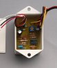
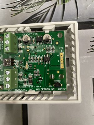
I have found a decent picture of the top of the circuit board that I can figure out most of the components on the board, but I cannot find a picture of the bottom of the board so I can figure out the complete circuit.
I can make out the resistor sizes, LM331N and trim pot but I cannot see what the value of the capacitors and diodes are. Would someone be able to take a few good photos of the bottom and top of the circuit board and post them??
I have been keeping an eye out on Ebay for one but haven’t seen one yet. Would anyone have one for sale?
I am hoping to make a couple of them so I can control the pool solar heater as well!
Thanks for the help!
From KB.HOMEAUTO.COM
Calibrating the 14A00-8 Water Temperature Sensor and 1101A PESM
The temperature can be calibrated by using the potentiometer on the device. Turn the potentiometer clockwise to "lower" the temperature. Turn the potentiometer counter-clockwise to "raise" the temperature.
The system only updates the temperature every 30 seconds. For a proper reading, wait 60-90 seconds after making an adjustment to the potentiometer.
If you have a meter that reads frequency, the temperature (in frequency) can be read over a DC square wave. Put your meter between the black and yellow wire and measure the frequency.
FREQUENCY = (4 TEMPERATURE) / 30
Example:
If the ambient temperature is 75 degrees:
FREQUENCY = (4 75) / 30
FREQUENCY = 300 / 30
FREQUENCY = 10 Hz
I'm hoping to get some help with finding or building a 14A00-8 Water Temp Sensor for my pool. From the pictures I can find online it seems to be a very basic circuit board with an LM331N which takes the voltage output from the temp sensor and converts it to a frequency. The HAI Knowledge Base website has some information about it. Mainly temperature to frequency calculation (FREQUENCY = (4 (temp)) / 30. I have placed a meter on one of my other outdoor sensors and did get a frequency that, when I did the math, came out to the correct temp so it seems that all HAI’s temp sensors work the same way.
I have found a decent picture of the top of the circuit board that I can figure out most of the components on the board, but I cannot find a picture of the bottom of the board so I can figure out the complete circuit.
I can make out the resistor sizes, LM331N and trim pot but I cannot see what the value of the capacitors and diodes are. Would someone be able to take a few good photos of the bottom and top of the circuit board and post them??
I have been keeping an eye out on Ebay for one but haven’t seen one yet. Would anyone have one for sale?
I am hoping to make a couple of them so I can control the pool solar heater as well!
Thanks for the help!
From KB.HOMEAUTO.COM
Calibrating the 14A00-8 Water Temperature Sensor and 1101A PESM
The temperature can be calibrated by using the potentiometer on the device. Turn the potentiometer clockwise to "lower" the temperature. Turn the potentiometer counter-clockwise to "raise" the temperature.
The system only updates the temperature every 30 seconds. For a proper reading, wait 60-90 seconds after making an adjustment to the potentiometer.
If you have a meter that reads frequency, the temperature (in frequency) can be read over a DC square wave. Put your meter between the black and yellow wire and measure the frequency.
FREQUENCY = (4 TEMPERATURE) / 30
Example:
If the ambient temperature is 75 degrees:
FREQUENCY = (4 75) / 30
FREQUENCY = 300 / 30
FREQUENCY = 10 Hz