Super interesting thread Pete! I've been wanting to build something similar for a while now, keep posting details please. I've been on the fence about doing a project like this due to the many fake cells, market being flooded with sketchy BMS products and concern about temps due to being exposed to the sun.
You are using an out of date browser. It may not display this or other websites correctly.
You should upgrade or use an alternative browser.
You should upgrade or use an alternative browser.
Pete's Blog HOW LIGHTNING WORKS and use of automation methodologies
- Thread starter pete_c
- Start date
Blog posts by pete_c
pete_c
Guru
October 18, 2023
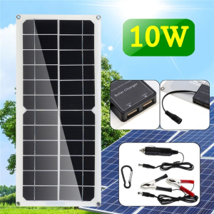
First time testing new solar panel (18VDC) X 10 watt.
Waveshare Semi-Flexible Polycrystalline Silicon Solar Panel (18V 10W), Supports 5V Regulated Output
~$20 on Amazon - $10 on Ebay.
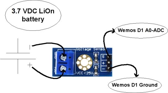
Adding a battery monitor to a0 - ADC - to one of the Wemos D1's.
Voltage Divider Calculator
First time testing new solar panel (18VDC) X 10 watt.
Waveshare Semi-Flexible Polycrystalline Silicon Solar Panel (18V 10W), Supports 5V Regulated Output
~$20 on Amazon - $10 on Ebay.

Adding a battery monitor to a0 - ADC - to one of the Wemos D1's.
A fully charged 18650 battery voltage is 4.2V. So to measure this voltage we have to step down the voltage by using a voltage divider network.
The Wemos D1 mini already has an internal voltage divider that connects the A0 pin to the ADC of the ESP8266 chip. The voltage divider is made up off 220k (R1) and 100k (R2). So, we have to add an external resistance with the inbuilt 220k resistor to read the battery voltage. By using a 100k resistance we can measure the max voltage (4.2VDC) of the 3.7 VDC battery, but taking some margin, a XXXk resistor is selected using this calculator ==>
Voltage Divider Calculator
Last edited:
pete_c
Guru
Mostly watching what temps will do to the battery.
Neighbor went to using a car battery with his solar panels and outdoor landscaping lightning a few years ago.
Update - cloudy and rainy today. Solar panel did work some charging battery one notch of four. Yesterdays sunny day charged up batteries within a couple of hours.
Update October 20, 2023
Adding another battery pack which should give me maybe 48 hours of run time with no sun.
Update October 22, 2023
Wired in temperature sensor. Charging 4 battery 18650 battery pack today.
Could not get the ADC input working correctly with a resistor. (analog input value).
Last edited:
pete_c
Guru
Update October 24, 2023
The four battery pack works along with the solar charging. Noticed yesterday that battery pack got fully charged with a couple of hours of sunlight. This morning before sun rise battery pack is at 3 bars of 4 bars. Purchased an external voltage splitter and trying the voltage meter sensor thing again.
Update 2 - battery pack is fully charged at 1300c time. Also purchased a 12VDC to 5VDC automotive style Bucky transformer that I can connect to the Landscaping lighting transformer which is 12VDC and goes on at night.
The four battery pack works along with the solar charging. Noticed yesterday that battery pack got fully charged with a couple of hours of sunlight. This morning before sun rise battery pack is at 3 bars of 4 bars. Purchased an external voltage splitter and trying the voltage meter sensor thing again.

Update 2 - battery pack is fully charged at 1300c time. Also purchased a 12VDC to 5VDC automotive style Bucky transformer that I can connect to the Landscaping lighting transformer which is 12VDC and goes on at night.
Last edited:
pete_c
Guru
October 26, 2023
It rained most of October 25, 2023. There was some battery charging going on yesterday. My only reference right now is the solar panel to battery "bars". IE: in the morning yesterday it started at 2 bars and went up to 3 bars before the sun went down.
This morning October 26, 2023 the battery state is at one bar. Overcast this morning. Voltages for battery are: 3.0 VDC (cutoff) to 4.2 VDC where as it sits mostly around 3.7 VDC. Note that battery pack is 4 2500mAh 18650 batteries ( 1 1000mAh total). Charge rate maximum is 1000 mAh with no adjustment.
Testing voltage on ADC on another Wemos D1 / LiOn battery and ADC pin. Range setting compared to actual battery voltage.
I want to do this all with Tasmota rules versus changing the variable value in Home Assistant. Connectivity will be one pin (5X less voltage) and ground pin from battery to Wemos D1.
So test configuration did this:
Actual LiOn battery voltage is 4.13 VDC (using a multimeter)
Set range this way:
AdcParam 6,0,1023,0,1504
To give me a range 413 value
and these rules:
rule1 on SYSTEM#BOOT do adcparam 6,0,1023,0,1504 endon
rule1 on
Last edited:
pete_c
Guru
Another addition:
MAX17043: Battery Monitoring Done Right (Arduino & ESP32)
Building a battery-powered IoT device? Then you'll want to monitor the battery's percentage. Here's how to do it properly.
The problem
Many websites tell you to measure the battery level by measuring its voltage. Usually with a voltage divider to bring down the voltage so that an ADC can read it.
But this method is not ideal. First up: it continuously drains the battery (depending on the resistors you use). And secondly, the voltage of Li-ion or LiPo batteries doesn't drop linearly. The voltage drops off quickly in the beginning, stays very stable for a long time, and then suddenly drops low at the end of its life:
It's challenging to convert a measured voltage into a battery percentage.
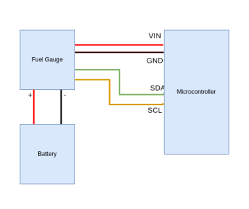
Fuel Gauge: MAX17043
A better solution is to use a "battery fuel gauge," such as the Maxim Integrated MAX17043 (datasheet).
This tiny chip uses the ModelGauge algorithm to measure a battery's capacity. It doesn't require resistors or calibration.
It works through an i2c interface, and it can report the battery's percentage and voltage. It also has an interrupt pin, so you can have it wake your microcontroller when the battery dips below a certain level.
And even more good news: it's available as a breakout board for DIY projects, such as these from DFRobot or Amazon.

pete_c
Guru
November 1, 2023
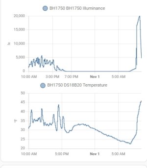
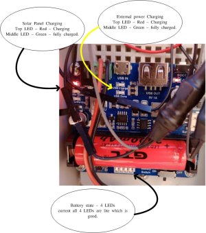
We had snow and sun yesterday with temps dropping down to the 20's. Batteries did charge with the sun for a little bit then solar panel got covered with snow. Doing only visuals of LED charge indicators and battery indicators on board. This morning it is sunny, solar panel covered with snow and one of four bars of battery are illuminated. Poured hot water on the solar panel to remove snow / ice on it. Panel immediately starting charging battery bringing level to 2 bars after 15 minutes.
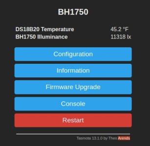
This is the current light level (sunny) and inside of box temperature. Outside temperature is currently 28 F. The Wemos D1 boards must be generating some heat or it appears that when I cleaned the solar panel then temperature went up inside of the project box. Moving the temperature sensor to batteries today.
Found that Amazon has a bunch of cheapo solar panels (junk clones).
I do not think the one I purchased is junk. (10 watt). Batteries are showing fully charged now at around 1350 C time which is good.
Waveshare Semi-flexible Polycrystalline silicon Solar Panel (18V 10W), Supports 5V regulated output
Using an amp calculator shows it at 0.56 amps when charging. Solar charging circuit allows up to 1 amp of charging. Purchased a second solar panel today.


Last edited:
pete_c
Guru
Tuesday, November 7, 2023
Works with Sunny day and cold weather. Noticed that the charging warms up the box. That said the solar panel / full sun never fully charges the batteries. Adding one more battery and a second solar panel to see if I can fully charge the battery on a sunny day and get more days of no sun.
Found out I can put more than one i2C device on one Wemos D1. That said my compact my set up some and maybe go to an ESP32. It is the radio that utilizes the most power.
I do have more Wemos D1 boards, BH1750 and another AS3935 board to test with.
Found out in the last few days that the MAX17043 code has been written for the Tasmota firmware but never incorporated in to the firmware unless I want to do it manually. Opened a ticket for this and doing a request that the Max17043 i2C chip be included in the standard Tasmota-sensors bin.
pete_c
Guru
Update November 13, 2023
Using two 10 watt solar panels now. IE: 20 watts. Added another LiOn battery (2500mAh X 5).
On a sunny day battery meter goes to 4 LEDs and stays there overnight.
That said Solar Panels are not fully charging the batteries as LED charging status remains red and has only gone to green once.
Might add another solar panel. It doesn't matter much with temps going to freezing here in the midwest. When sunny charging continues to work and generate heat inside of the project box. I can maybe trigger a 5VDC charge when its been cloudy for a couple of days using an automotive style 12VDC to 5VDC bucky transformer. The 12VDC landscaping transformer is mounted on the deck a few feet away from the weather mast.
Will be testing two i2C connections to one board soon. IE: Luminance and Lightning and temperature.
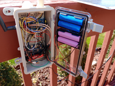
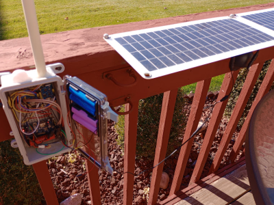
Here is what the configuration looks like outside. Note this is just for testing. Eventually will mount the device on the Davis weather station mast.


Last edited:
pete_c
Guru
November 19, 2023 Update
Removing one Wemos D1 device today and combining all of the sensors to one Wemos D1. The device should utilize less power now with only one radio active.
Today connected the BH1750 ambient light sensor and the AS3935 Franklin Lightning sensor and DS18B20 Temperature sensor to one Wemos D1 and disconnected 2nd Wemos D1.
Both are i2C sensors with two different addresses. It is suppose to work fine this way and it does.
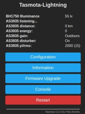
Next adding the 1-Wire sensor (3 wires). Works fine.
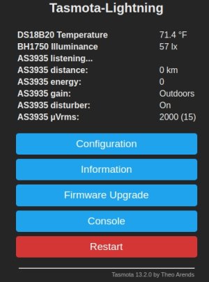
Next here disconnecting one unused Wemos D1 and tie wrapping - grouping wires before putting it back outside.
Happy camper here; worked as documented.
Removing one Wemos D1 device today and combining all of the sensors to one Wemos D1. The device should utilize less power now with only one radio active.
Today connected the BH1750 ambient light sensor and the AS3935 Franklin Lightning sensor and DS18B20 Temperature sensor to one Wemos D1 and disconnected 2nd Wemos D1.
Code:
Wemos D1 ==> SCL (GPIO5) +SDA (GPIO4) ==> BH1750 and AS3935 i2C devices
                   ==> GPIO15 (IRQ) ==> AS3935 IRQ
                   ==> GPIO14 ==> DS18B20 temperature sensor
                   ==> 3.3VDC ==> BH1750, AS3935 and DS18B20
                   ==> ground ==> BH1750, AS3935 and DS18B20
Both are i2C sensors with two different addresses. It is suppose to work fine this way and it does.

Next adding the 1-Wire sensor (3 wires). Works fine.

Code:
19:10:18.497 CMD: i2cscan
19:10:18.519 MQT: stat/Tasmota-Lightning/RESULT = {"I2CScan":"Device(s) found at 0x03 0x23"}

14:57:41.443 MQT: tele/Tasmota-Lightning/SENSOR = {"Time":"2023-11-19T14:57:41","DS18B20":{"Id":"3C71E381C3E4","Temperature":68.1},"BH1750":{"Illuminance":16694},"AS3935":{"Event":0,"Distance":0,"Energy":0,"Stage":15},"TempUnit":"F"}
Next here disconnecting one unused Wemos D1 and tie wrapping - grouping wires before putting it back outside.
Happy camper here; worked as documented.
Last edited:
Similar threads
- Replies
- 0
- Views
- 1K
- Replies
- 0
- Views
- 2K
- Replies
- 1
- Views
- 2K
- Replies
- 11
- Views
- 2K
