how would i wire an analog camera? more specifically, i think i understand the use of baluns to get the signal to travel over cat5 to its destination. what i wonder is what the power source would be. that is, if i wire an analog camera to the outside of my house, and the wire access is to the attic, where does the power supply come from? i don't think i have any plugs in my attic. what's the standard answer for this sort of thing?
You are using an out of date browser. It may not display this or other websites correctly.
You should upgrade or use an alternative browser.
You should upgrade or use an alternative browser.
how to wire an analog camera?
- Thread starter DeLicious
- Start date
johnboy70_99
Member
how would i wire an analog camera? more specifically, i think i understand the use of baluns to get the signal to travel over cat5 to its destination. what i wonder is what the power source would be. that is, if i wire an analog camera to the outside of my house, and the wire access is to the attic, where does the power supply come from? i don't think i have any plugs in my attic. what's the standard answer for this sort of thing?
These cameras usually come with a "wall wart" type power supply. I have 4 of them. I ran RG-6 for signal and 18/2 for power from the camera location to my central control position in the basement. Then I cut the power supply cable that comes with the camera and spliced it into the 18/2 wire run. U used adaptors for the RG-6.
You should have a distributed power supply located at the DVR, the power is run over either 18-2 along side the Cat5 or in the case of low powered cameras you can run it over the Cat5 itself. There is no need for a balun to have power connections you can simply add the power barrel yourself.
what if my DVR is a computer? i guess i'm unsure what a distributed power supply is exactly.
The power supply goes outside the DVR usually wall mounted, one is included in old CT combo #3 it has 4amps of current and PTC protection (auto reset circuit breakers) on it's outputs.
SnyperBob
Active Member
You can buy premade wires off eBay as well. They include an RCA cable for the video feed, and a power cable. You run the cable from your camera to your wiring closet/dvr.....your wall wart plugs in near your DVR and it's simple. No expensive baluns and custom wire fabrication
You can get them up to 100 foot lengths I believe. This one is like $15 including shipping:

You can get them up to 100 foot lengths I believe. This one is like $15 including shipping:
SnyperBob
Active Member
Here's an example of a distributed power supply. You run the power cords for all of your cameras into something like this. Then you only have to plug in this one module to send power to all of your cameras. Now, I'm not sure if the one in the picture is what you would need for cameras, it's just an example....:

For distributed power, I have started using these and love them.
http://www.elkproducts.com/products/elk-pd9.htm
overload proctection on each output, outputs can be combined for higher loads, and the LED's provide quick visual status.
The pre-made video and power wires are great, but sometimes very difficult to pull through walls or pipes as needed.
StevenE
http://www.elkproducts.com/products/elk-pd9.htm
overload proctection on each output, outputs can be combined for higher loads, and the LED's provide quick visual status.
The pre-made video and power wires are great, but sometimes very difficult to pull through walls or pipes as needed.
StevenE
BraveSirRobbin
Moderator
At least with THIS one, you can parallel the outputs for more current capability.I have a PD9 with battery backup installed as well, works great. I use it to power some of my other accessories as well. I wish it supported higher current loads tho.
BraveSirRobbin
Moderator
Right, you have the wrong item if you need more current capability. Take a look at the Elk-PD9HC. It has 400 mA rated outputs and the overall current draw is whatever your input supply can handle (looks like four amps at 12 volts DC is the 'max').That's the one I have, but look at the maximum current draw.
")
SPECIFICATIONS:
• Max Current Draw: PD9HC = 400mA from each output.
• Max Combined Current Draw: Not to exceed Input Power Source (or 4 amps @ 12vdc according to the PDF manual)
• Input/Output Voltage: 6 to 30 Volts AC or DC.
• Input Connection: Screw Terminals or 2.1mm Plug-In DC Jack.
• Output Connection: Screw terminals (POS and NEG) for each output.
• Enclosure Size: 6.5" x 4.3" x 2".
BraveSirRobbin
Moderator
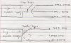
Something else might be worth mentioning here as well. I'm guessing some outdoor cameras require more current capability, therefore a large current capable supply is needed. One thing to keep in mind (as I'm sure most members here already know) is to be cognizant of the output's fuse method of the parallel "multiple" legs.
For instance in the first example below, the overall DC output is fused and the output is fed to three different sources. The problem is if source 1 shorts, the maximum current is fed down that leg (that the fuse will allow). Since your fuse size is probably comparable to the overall output amperage capability it may be more than desired (depending on the device, wire size used, etc...).
It's probably better to individually fuse each leg (near the distribution point) and size the fuses to each load's needs (second example below). This is the advantage of using a power distribution module such as the Elk's, but if its (current) capabilities are not large enough, you may need to implement your own protection scheme.
Attachments
Similar threads
- Replies
- 4
- Views
- 597