Monitoring water softener salt tank

electron

Administrator
Staff member
I think I have asked this before, but can't find any reference to it. I basically want HS to know how much salt my water softener system has left. I came up with a good idea (I think), assuming I someone can identify the part I need. I would drill a tiny hole through the top cover, and use some string and weights to activate some switches.

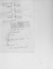
this is an ascii drawing of what I think would be a good setup:
Code:
             ___ [switch 1] (when activated, 90% salt remaining)
            /___ [switch 2] (when activated, 50% salt remaining)
           //___ [switch 3] (when activated, 10% salt remaining)
          ///
.------[|||]-------.
|       |||        |
|       O||      s |
|        ||      a |
|        ||      l |
|        ||      t |
|        ||        |
|        O|      t |
|         |      a |
|         |      n |
|         |      k |
|         O        |
|                  |
|__________________|

x = small weight
| = string

So all I need is the opposite of a push switch, so when the tank gets down to 90%, switch 1 will activate as the weight is 'hanging' now instead of resting on top of the salt, switch 2 will also activate when the remaining salt level goes down to 50%, and the same for switch 3. This way the only item in the tank will be some string and a dead weight, so I don't have to worry about electronics/switches being exposed to the salt/water. Can anyone see a reason why this wouldn't work? Also, if someone could point out the part I need on the RadioShack website, that would be great!

I am even thinking about using resistors for this setup so I only need to use 1 input on my Ocelot.
 
Yes, there were a few ideas tossed around. I suggested using a magnetic door contact electric switch side on the outside top of my flat plastic lid covering the salt. Inside would be the magnet attached to a string with enough length to connect to a plastic float ontop of the salt. As the salt level dropped so would the float which eventually would pull the magnet sending a zone alarm to my alarm system which then tells Homeseer. You could probably toggle a hacked X10 wireless motion sensor so you don't have to run a cat5 cable to the softner.

You could also do same with a few contacts on the outside side with a float running on guides inside the drum. Then, magnets mounted to the side of the float that would trigger the contacts. Would probably not be as reliable to get multi level awareness. Not sure I need this added complexity. I just need to have a week head start reminder to buy salt.
 
I'm thinking of a more high tech aproach. I'm looking into the details for you now but maybe there will be an EE on this board that can assist with my idea. This idea could be used for more than just a water softner.

SONAR...

http://www.robotprojects.com/sonar/scm.htm
http://www.robotprojects.com/sonar/sonarprj1.htm

The above links use the "Polaroid Pronto One Step Sonar camera" and talk about how to utilize the sonar circuit from the camera. Perhaps with the help of "Smee" or one of the other guys who can program PICS and Motorola Microprocessor you could develope a very reliable and accurate system. Most of the work has already been done for you.

Again I will be looking into this more for you. Those cameras are sitting at E-bay right now for a max price of $15 and a min of about $8... I am going to try and pic one up just so i have it. At that price you cant beat it!
 
I remember this discussion from before, somewhere.

If you want to take your weight/string/switch approach, I'd consider using microswitches. Something like these from Radio Shack [1]. There are many different configurations out there. Note that most of them do not require much force to trigger.

As you show in your diagram, three of these with weights and the right length strings will provide your data.

You can configure these like little fishing poles - the string hanging from the end of the arm. You may want to extend the arm a bit. They will work exactly like the magnetic switches you are rigging for the garage door.

In order for this to work, you need to make sure that the strings don't get tangled up in anything. If you leave the slack inside the tank, they may become stiff (salt and water) or tangled. If you leave the slack outside, you need to make sure that it doesn't catch on anything. This will prevent the switches from triggering.

You could replace the strings with vertical rods (wire or dowels) if you don't mind them sticking up above the tank. Put a weight/float on the lower end of the rod (inside the tank). Put a disk on the top end (outside the tank). Glue a small guide tube (an inch or so long, maybe) above, below, or through the hole in the lid. The rod will slide inside this tube. This will keep the rod vertical. Position the switch so that the upper disk depresses the switch (or pushes it to the side, depending on how you mount the switch) when the rod reaches its lowest position.

I'd prefer a nice analog solution, but this approach is very simple and should work well with the Ocelot.


[1] Some other sources:
www.mpja.com
www.bgmicro.com
www.allelectronics.com (search for "lever")
Most of the "surplus" electronics places have them.www.allelectronics.com
 
For the switches, you could use regular microswitches (most have both a normally open and normally closed contact) arranged to have the weight pull downward on the arm. A switch like this one mounted horizontally:

http://www.radioshack.com/product.asp?cata...%5Fid=275%2D017

could be rigged to have the string go over the roller, or tied just behind the roller wheel and going over or around the end so that the lever would get pressed down by the weight when its let loose by the absence of salt.

Using several of these with different resistors on a single SECU16 input is a good application for the analog mode.
 
Thanks guys, that's exactly what I was looking for, I am going to try to use these resistors to find out what the level of salt is since this isn't a critical application, and allows me to play with switches and resistors. The slack will stay in the tank for the reasons mentioned above, I was thinking about maybe using fishing wire or something else that will work well with salt water. Not sure yet what weights I will pick (maybe a ziplock bag/balloon with some of the salt in it) as they aren't allowed to float (or the weights wouldn't go past the water level).

Maybe I can even add a magnet to the big dial on the water softener itself to find out when it is running, how long, and do the math on how long the remaining level of salt will last according based on the current programmed the water softener cycles.
 
no power needed. the 3 leads are a common, a NO (normally open) and a NC (normally closed). You would pick the common and one of the other two, depending upon what your Ocelot prefers.
 
The nice thing about the resistors thing is that you can bench test it first by just putting them in series and then shorting them out to simulate the switches being closed. All you need to do is then write a two line C-Max program to read the analog value and capture it in a variable. Then you use the C-Max utility "debug timers and variables" to watch the analog value change as you simulate the various conditions. The two line program is like this:

IF Module #1/Analog #1 is < 256 //example input #1
THEN Load Data to Variable #2 //store in variable #2

The variable can also be read by an external program like Homeseer.
 
I just realized that the garage door scenario uses 2 switches, I want to use 3 switches so i know exactly when it hits 50%, what would change and how?
 
Hmm, at the risk of further ridicule, hehe, I am resubmitting this idea of using three resistors and one Secu16 input. You have three resistors in series as shown in the schematic below. You have a specific resistance (i.e. analog) value for each situation, closed, open, middle, or "travel" which would indicate either 1/4 or 3/4 open.

You could then use logic to tell the difference between the 1/4 to 3/4 reading. In other words set and reset flags with the known positions and compare the flags to the "travel" positions.

I realize that the once the garage door got past the middle position that reading will be "travel" BUT you could place a lot of magnets along the middle "range" of where you wanted the garage door to be when (plus or minus height) when you wanted it to read "middle". Also you could use garage door sensors and magnets which have a wide gap to minimize the number of magnets you would have to use.

The only problem I see is I don't know enough about the Ocelot/Secu16 analog settings to see if it can discern four distinct readings? Need Guy's expertise here for that! If it can only discern say three readings, then just cut out a resistor leg and use two SECU16 inputs instead of one.

Maybe I'm not seeing the whole picture here so please feel free to comment on a better approach, or please point out how this scenario will not work.

Thanks,

BSR
 

Attachments

  • garage0004.JPG
    garage0004.JPG
    22.1 KB · Views: 42
You would need a third switch and another resistor. The three resistors could use values like 330 ohms, 1k and 3.3k . You should then try it on the bench and read the actual analog readings that you get when each one is shorted out in turn.

In this application, you might also take a simpler approach if you assume that the top, middle, and then lower switch will close in turn. Just use equal value resistors (1k would be fine) and as the total resistance gets lower, the analog value will go down. The different value resistors (to distinguish which switch is closed) are no longer needed in a case like this.
 
Guy:

I replaced my schematic with your suggested resistor values for electron's garage door application.

The total resistance value would be as follows:

Open = 4300 ohms
Middle = 3630 ohms
Closed = 1330 ohms
"Other" (3/4 or 1/4 open) = 4630 ohms.
 
Back
Top