Dryer exhaust/vent monitor

Ira

Active Member
I've seen a few products over the last few years that set off an alarm when the dryer vent gets too clogged up, but none of them are "smart home friendly", in that they don't have a way to connect to a HA control. I've also seen some devices that a repairman can use to measure the backpressure.

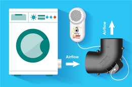
Has anyone figured out a way to DIY something like this? Most of them worked by monitoring the backpressure in the dryer exhaust duct, and if it got to high, sounded an alarm. I guess the hard part would be finding a way to secure it to the flex duct between the dryer and the fixed duct. Also might be difficult to find a pressure sensor that would work well for this. I guess the "normal" pressure range can vary depending on the dryer and ductwork. One of the products I saw also had a temperature sensor, and would alarm if either the temperature or the pressure got too high.
 
I'd love a DIY back pressure sensor (want to monitor my HVAC as well), but I haven't found anything.

I've been thinking about the dryer vent as well, and the only thing I can think of is an external temp sensor near the vent, and trigger an event should the temperature not rise as much as expected (weather shouldn't matter I think).
 
I bought a DrySafer on Ebay (at about half the Amazon price) last week to get a better idea of what it does. The provided ell that goes between the dryer and flex duct has a flapper in it that, when in the closed position, closes off about half the ell. The instructions say that the ell can point left, right, or up, but not down. That's because the flapper is positioned such that it is closed when the ell is pointing right/left/up, but open when it is pointing down, i.e., it controlled by gravity when the dryer is off.

I assume that when the dryer is running and the flapper is open enough, everything is okay. What I don't know is how it tells if the flapper is closed because the duct is clogged or because the dryer is off. To bench test it, I'm simply pointing the ell up, reaching in and opening the flapper to simulate air flow, then slowly closing the flapper. I haven't been able to make the alarm go off yet. I don't know if I'm doing something wrong or the unit is defective. It does power up correctly. But when I do the documented "system check" while holding the flapper open, it doesn't signal a "stuck open" flapper like it should.

I don't think I care for this product's approach (flapper position). About five years ago, I talked to the manufacturer of the "Lint Alert" (which it seems is no longer being produced) to see if they had plans to make something more smart home friendly. The answer was no, so I didn't buy one. However, it looks like at some point they came out with a Wifi model that talked to their mobile phone app. The Lint Alert used a pressure sensor that was tapped into the flex duct.

Here's a link to an article about dryer vent backpressure, etc. This is the company that used to make the Lint Alert. According to the article, the maximum back pressure should be less than .6 wci, so that gives us an idea of the range needed for a pressure sensor. Rather than signal an alarm when the backpressure hits .6 wci, I think a better approach would be to keep track of the backpressure trend to see the pressure increasing as lint builds up. Of course, if it got to .6 wci, then an alarm could be triggered.

I assume you would want a pressure sensor capable of sending a 4-20 mA signal based on the duct backpressure. The sensor would have to have a low pressure range (the magnehelic gauge in the article was 0 to 2 wci). Any idea if something like this is available for less than the cost of a good dryer? Probably wouldn't need a different way to tell if the dryer is on or off, since a pressure reading of zero would imply it's off.

Would this $75 sensor work?

I see that some manufacturers (Samsung, LG, and probably some others) have dryers with backpressure sensors. Seems like a no-brainer.

I too would like to do the same with my HVAC system.
 
I looked at the air pressure sensors for aerobic septic systems. They actuate at 1 psi, which is about 28 wci. Too much pressure for what you need. To build a sensor with that low air pressure you would need a large diaphragm connected to a tube that does not plug with lint.
 
The one that I linked to in my previous comment is 0 to 1, 0 to 2, or 0 to 5 wci. Seems like the first two would work.

Not sure how to keep the probe from plugging up. Maybe that's why the Lint Alert isn't being manufactured anymore.
 
Ira, that $75 sensor should work if that is indeed the pressure ranges you would need. It has a 0-10 volt output that you could monitor in a variety of ways. If you needed a contact closure to alarm at a certain reading, you could use a voltage comparator and a relay. I had such a circuit in my

[How-To] Interface a Dexcom Diabetes Monitor to your Home Automation System

but I need to have Electron look for that with this new forum.
 
That sensor is a differential pressure sensor. I think this project needs a static pressure sensor. Would I need to cap the low pressure inlet or leave it open?
 
Here's the solution I'm leaning towards. Note that I'm thinking about using the Hubitat Elevation as an automation hub for this and other stuff. I bought one a few weeks ago to play with...

1. Neptronic pressure sensor ($75) to monitor pressure and put out a 0-10Vdc signal.
2. Fibaro Smart Implant z wave device ($40) to convert the voltage signal to a numeric pressure value that can be polled by the Hubitat. This device also supports temperature sensors, so I could monitor backpressure and temperature at the same time with one of these if I add a temperature probe. The "Shelly Uni" ($16) is a similar device, but it is Wifi instead of z wave, doesn't have an enclosure, and doesn't have a fully supported Hubitat driver.
3. Hubitat polls the Smart Implant every few seconds when dryer is running. Several options available to determine when dryer is running, including z wave outlets that have power monitor capabilities.
4. Some way for the Hubitat to analyze the realtime data it is receiving, and maybe compare it to historical data. Haven't looked into this yet.
5. If backpressure is trending up at a significant rate, or if pressure reaches predetermined level(s), trigger a Hubitat event (or maybe trigger an M1 zone). Could also "turn off" the dryer if the pressure gets close to high. A z wave outlet could do this since it's a gas dryer.

I think the same approach could be used for monitoring HVAC systems. If the HVAC filter is located in the ductwork instead of at a return air grille, the pressure sensor could monitor differential pressure across the filter instead of static pressure in the duct. I think that would be more valuable.

Comments?
 
I have all the components on order, and am trying to understand how this all wires together. Here's the link to the Fibaro Smart Implant manual...

https://manuals.fibaro.com/content/manuals/en/FGBS-222/FGBS-222-EN-T-v1.2.pdf

...and the link to the Neptronic pressure sensor doc...

https://www.neptronic.com/controls/pdf/SPD070-161031-ESA.pdf

Page 4 on the Implant manual shows how to wire a 2-wire analog input and a 3-wire analog input. So I'm already stumped. I can't tell from the Neptronic sensor doc which one it is. I do know that I need to use 0-10Vdc output from the sensor because the Implant doesn't support 4-20mA input. Hopefully, the sensor can be used as a 3-wire sensor because it looks like a 2-wire sensor will cause other issues, like maybe requiring different power supplies. The sensor can be 24V AC or DC. The Implant can be 9-30Vdc for 3-wire, but seems to require 12Vdc for 2-wire.

Can someone please take a look at these two documents and tell me in layman's terms how to wire this thing, e.g., connect the wall wart + to sensor terminal #2 and Implant terminal "P". Connect sensor terminal #3 to Implant terminal "?", etc.

Other than the hubitat, I don't think anything else is needed for this. Communication between the hubitat and Implant is via z wave.
 
Looking over this quickly, I believe you just connect the two devices as shown, but hopefully a forum member can verify this.

You will have to convert the 0-10 volt to 0-1" WC (as that is the scale of the device you selected), so basically just divide the measured voltage by 10.

Ensure you have your input #1 configured to analog and not digital on that Z-Wave device.
 

Attachments

  • Circuit.jpg
    Circuit.jpg
    88.4 KB · Views: 6
Thanks for the diagram. I think everything I need to bench test it will arrive before the weekend, so I hope to bench test it over the weekend.
 
I have most of the components now, so I was able to do some bench testing. As previously mentioned, I have the Neptronic pressure sensor (0-1 wci) to output a 0-10Vdc signal (based on the pressure) to the Fibaro Smart Implant multi-sensor, which is communicating via z-wave with a Hubitat Elevation controller. I'm using on 24Vdc 4A transformer to power both of them. Logically speaking, the components are wired together the same as shown in BSR's diagram. The sensor's low side pressure port is open to the atmosphere. I have a tube connected to the high side pressure port that I can blow into to simulate dryer back pressure.

I used a volt meter to validate the 0-10V voltage when I blew into the hose, and the voltage increases as expected. I can also see the increasing voltage on the Hubitat "dashboard", which is polling the Smart Implant every two seconds.

Now I need to figure a way to connect the pressure sensor to the dryer exhaust duct to get some "real world" experience.
 
Don't forget about the operating temperature limitations. Looking forward to your results!
 
Back
Top