Hardwired Lighting System Using Cat5

Hi Wayne,

I agree there is a lot of parts to choose from, but i think i got it narrowed down pretty good now since i am placing my order soon. The informatio below is all resulting from my studies of this system and not tons of years of practical experience. The recent documents posted by Tony Stewart have been a great help, they are here nut you do need to register with SetNet (which is free and doesnt commit you to anything) to view them.

I guess it large depends on the size of the installation, but as a base for any size installation using ELK control it appears you need part number 364864-01 Lighting Interface, ALC to ELK M1 Automation Controller. It will do the basic communication between the ELK and ALC systems. This is a single product that connects directly to the ELK databus (hub).

If you don't go the ELK route and want to have something else control the lights (e.g. CQC) then you woudl need the following parts: 364644-01 Lighting Controller, ALC, Home Lighting Controller AND 364698-01 Lighting Interface, ALC, Serial Expansion Module.

From here on out its all the same no matter if you use ELK or something else to control the lights.

The above setup will give you 1 'branch' or 31 adresses (each dimmer/relay switch and scene switch needs an adress, AUX switches don't need one). If you need more than 31 adresses you will need part 364726-01 Lighting Interface, ALC, Expansion to create the additional branches.

The description below describes 1 branch, it woudl apply if you have the single branch of the normal or ELK controllers but also applies to each of the 3 branches of the expansion module.

The branch starts with a RJ45 port on the controller or expansion module. From there on out you can connect to the house in many many different ways. You can daisy chain from device to device or you can do single or multi level star topology. They all have limitations on their total cable length.

From my understanding for shorter cable runs you can simply use the 364645-01 Lighting Interface, ALC Distribution Module. This essentially functions as an ethernet hub and just provided a neat way to tie all the wiring together for you. For longer runs (or for those you want to be more 'safe') you can use 364677-01 Lighting Hub, ALC Branch Hub AND/OR 364736-01 Lighting Hub, ALC Branch Hub, Enhanced. Either one of these conditions and boosts the ALC communication signals for longer cable runs. The difference between then is the dipswitches on the enhanced hub so you can switch cable runs of and on during troubleshooting. Don't confuse each cable run from the hubs as a ALC branch, the hubs only tie the wiring together. You can only connect a maximum of 31 devices to each branch coming from the controller, not matter if you run it though hubs or anything else.

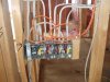
Initially i had planned to homerun cat5 from each switch location to the wiring room, but the quantity of runs i starting toget a bit rediculous and my conduits from basement to attic are starting to get full. I am thinking about changing strategy to put a box in the attic with some of the hubs and essential have 2 main locations to which everything is homerunned. The box is the attic will be reasonably accesible, but not as good as in the basement. Oh well..hopefully once it's all in i won't have to do much to it anymore.

This document has been a real eye opener for me and details very well how the wiring is done and the different options.


Well said! As far as sic0048's question about loaners, I will ask Onq to assist and advise you what I learn. Also the dimpled paddlesa re no longer available. Although we do have some color change kits and some of the dimpled paddles if you desire. Otherwise all other models are smooth and match any decora brand in shape/look. Colors are another matter. I could ship you some paddles for color samples.

TS
 
Actually it was WayneW that asked about the loaners. ;)

I think the flat switches (instead of the dimpled switches) are much better looking and I assume OnQ realized this too and that is why they discontinued them. When people say the ALC switches are ugly, I have to believe they are talking about the older dimpled switches - they were ugly.

I guess using the enhanced hubs make sense. But I am just trying to figure out if it is worth the approximate $8-10 per switch that the hub will cost. I guess it pays for itself the first time you have a problem and have to trouble shoot it however. It will also make wiring easier since you don't have to run every wire back to the control unit.

I assume you should connect multiple hubs together until you reach the 31 switch limit and then run a wire back to the control panel (or expansion unit if needed)?

Someone else asked this question earlier in the thread, and I don't think it was ever answered, What color is the LED on the ALC switches that have them? Also, I assume the LED comes on when the load is turned on. Is this correct or is there any other function for the LED? In other words, what is the advantage to installing switches with LEDs?
 
I'm still confused about attaching multiple hubs to a single branch. I've made an image of how I think it's done, wiring one enhanced hub to another, with a single CAT5e run down to the main location. Is this correct. In the picture I've included I've wired all my lights to an enclosure with a single cate out to the main control, even though I'll have 2 hubs on this level. Please let me know if I've got it right.

Thanks

CB
 

Attachments

  • hubs.jpg
    hubs.jpg
    42.6 KB · Views: 44
  • wiring.jpg
    wiring.jpg
    43 KB · Views: 31
Actually it was WayneW that asked about the loaners. ;)

I think the flat switches (instead of the dimpled switches) are much better looking and I assume OnQ realized this too and that is why they discontinued them. When people say the ALC switches are ugly, I have to believe they are talking about the older dimpled switches - they were ugly.

I guess using the enhanced hubs make sense. But I am just trying to figure out if it is worth the approximate $8-10 per switch that the hub will cost. I guess it pays for itself the first time you have a problem and have to trouble shoot it however. It will also make wiring easier since you don't have to run every wire back to the control unit.

I assume you should connect multiple hubs together until you reach the 31 switch limit and then run a wire back to the control panel (or expansion unit if needed)?

Someone else asked this question earlier in the thread, and I don't think it was ever answered, What color is the LED on the ALC switches that have them? Also, I assume the LED comes on when the load is turned on. Is this correct or is there any other function for the LED? In other words, what is the advantage to installing switches with LEDs?

The ugly comments were always related to the dimpled version.
The worth of the dip switches on the enhanced hub is to assist during install so that you can find polling loops that you crossed up the the wiring on (crossing up the + and - will shut down the entire branch until you uncross it and finding which switch is crossed is easy with the dip switches). And the dip switches are used after a lightning surge takes out a switch(s). Once installed correctly, failure is no longer an issue and as such the troubleshooting value of the dip switches is lessened.
Note that we have a polling loop surge protection device if you are in a location of the U.S. where electrical storms are a problem. The voltage of the Polling loop makes finding a surge protection module hard, but these will do the trick.

The versions that have an LED (which is Green) are the part number 36314x-2x. The ones that do not have an LED are part number 36314x-1x. X is the color of the paddle.
The LED's are ON when the switch is OFF!

We have found that homeowners HATE LED's. Well over 90% of ALC switches sold are the NON-LED versions. However, the techies like the LED's.

Those of you writing drivers for CQC or other devices can control the LED indicators as you desire. With the developers kit you can basically make the LED do anything you desire. However with the ELk and HAI controllers, it is not controllable from program flow.

TS
 
I'm still confused about attaching multiple hubs to a single branch. I've made an image of how I think it's done, wiring one enhanced hub to another, with a single CAT5e run down to the main location. Is this correct. In the picture I've included I've wired all my lights to an enclosure with a single cate out to the main control, even though I'll have 2 hubs on this level. Please let me know if I've got it right.

Thanks

CB

From your drawings it looks correct. I see all hubs paralled off of one of the 4 branches. This will work as drawn. But.... remember that the 12VDC power to the hubs will have a voltage drop. And since cat 5 is a 26 gauge cable, the drop will get worse as you add cable. To reduce this, double up on the 12VDC loop and use two pair or run additional cable.

TS
 
We have found that homeowners HATE LED's. Well over 90% of ALC switches sold are the NON-LED versions. However, the techies like the LED's.

Thanks. I had planned on getting plain switches without the LEDs, but this just confirms my thoughts.

Those of you writing drivers for CQC or other devices can control the LED indicators as you desire. With the developers kit you can basically make the LED do anything you desire. However with the ELk and HAI controllers, it is not controllable from program flow.

TS

Perhaps Beelzerob can modify the CQC driver to send out morse code status of different devices. ;)
 
Tony,

Whats the environmental conditions for the hubs? I was planning to do homeruns for all switching to the basement but am adjusting plans (reducing wire cost and time and uses less conduit space).

I am considering putting 1 or more hubs in my attic which is vented to the outside (so it's hot and cold in summer and winter). Putting the hub somewhere that is temperature controlled will not be so easy in my case, unless i put a 14x14 panel in my master bedroom closet or something which i really don't want to do.

Also is there a good may to mount these hubs into a structured wiring panel? They seem to be made for a 2 gang switch box.

If the temps allow it in the attic my plan was to nail a 2 gang new work box on one of the attic trusses and then run the cat5 from all upstairs switches to there and then a main run down to the wiring room in the basement. I would need only 1 switch that would have it's aux upstairs since a 2 cat5 runs woudl do the trick (2 wires for polling loop, 3 for aux, 4 for hub power (2 conductors ganged as recommended).

Is there a convention of some sorts that describes which color wires from the ALC devices connect to which color on the cat5 cables? I've found the following pigtails on the back of ALC devices.
--- For the scene switch we have:
------- Yellow TX+
------- Violet TX -

--- For the 600W dimmer we have:
-------- Yellow TX+
-------- White TX -
-------- Green AUX ON
-------- Red AUX OFF
-------- Black AUX COMMON

I don't have any other switches in house and the ALC documentation i have appears to not match the physical devices i have inhouse. If somebody has a relay and a AUX switch can they chime in with the LV colors and their function?

What i gather from the ALC documentation is:
TX+ = White / Blue
TX- = Blue
AUX Common = Brown
AUX ON = Orange
AUX OFF = Green
12 VDC = White / Brown (for the hubs)
Ground (for 12V) = White / Green (for the hubs)

I'm going to add this to my wiring color convention thread here for those interested.

One last issue/question:
Is it true that there is a max to the number of the Scene switches and do they really need to be on the first branch? If this is true this would make wiring a bit more complicated. For example i wanted to use 1 branch for the upstairs and another branch for the downstairs. If the scene switches need to be on a certain branch i would need to double up on the branch wiring for at least one of the 2 branches.
 
The versions that have an LED (which is Green) are the part number 36314x-2x. The ones that do not have an LED are part number 36314x-1x. X is the color of the paddle.
I am confused by 363143-11 http://www.setnetpro.com/product.asp?3=1972
It looks like a real switch, not an aux (3-way) switch, but states "Does not connect directly to the 120VAC load or system controller. ". Is that a typo? What do you do with it or what do you connect it to?
 
I'd love to see some pictures of real installs. Especially close up of the switches with the cover plate off. Also a picture of the "clip" that holds the cat5 on the back of the outside of the box.

People that are doing the "CAT5 inside" I'd like to see pictures of the inside before stuffing in the switch...

My building department guy doesn't like the CAT5 outside the box because he is convinced the switch will crush the LV wires against the edge of the box and short out. I pointed out that even if that did happen, the only downside is that the automation control won't work, and maybe the auxes for that one switch. He said that "capacitive effects" could lead to end user shocks, and code requires the box to stay at ground potential. As an MIT grad, I think he's an idiot. Fortunately I kept my opinions to myself. Even better, he isn't the guy doing our final electrical sign off.

Thanks -- Bob
 
Assuming all wires (including Aux) are run to the location of the enhanced hub, are these statements true:

1) When connecting switches in a 3 way setup, only one hub termination point is used.
2) when connecting switches in a 5 way setup, two termination points are used.
3) One must determine where the load enters the circuit in order to identify the master switch.
4) 3 conductor wires from the AUX switch must be run back to the enhanced hub where the master communication wires will terminate, even if this is on a different floor.
5) Scene switches require only 2 wires, Tx+ and Tx-.

As an aside, where would a scene switch be used in place of a standard switch? Or would a scene switch be more appropriately installed in addition to other switches?


btw here's how I ran my CAT5e to the switch location. I can provide a closeup if anyone wants to see the clips I used.

thx

CB
 

Attachments

  • boxes.jpg
    boxes.jpg
    53.4 KB · Views: 59
Tony,

Whats the environmental conditions for the hubs? I was planning to do homeruns for all switching to the basement but am adjusting plans (reducing wire cost and time and uses less conduit space).

I am considering putting 1 or more hubs in my attic which is vented to the outside (so it's hot and cold in summer and winter). Putting the hub somewhere that is temperature controlled will not be so easy in my case, unless i put a 14x14 panel in my master bedroom closet or something which i really don't want to do.

Also is there a good may to mount these hubs into a structured wiring panel? They seem to be made for a 2 gang switch box.

If the temps allow it in the attic my plan was to nail a 2 gang new work box on one of the attic trusses and then run the cat5 from all upstairs switches to there and then a main run down to the wiring room in the basement. I would need only 1 switch that would have it's aux upstairs since a 2 cat5 runs woudl do the trick (2 wires for polling loop, 3 for aux, 4 for hub power (2 conductors ganged as recommended).

Is there a convention of some sorts that describes which color wires from the ALC devices connect to which color on the cat5 cables? I've found the following pigtails on the back of ALC devices.
--- For the scene switch we have:
------- Yellow TX+
------- Violet TX -

--- For the 600W dimmer we have:
-------- Yellow TX+
-------- White TX -
-------- Green AUX ON
-------- Red AUX OFF
-------- Black AUX COMMON

I don't have any other switches in house and the ALC documentation i have appears to not match the physical devices i have inhouse. If somebody has a relay and a AUX switch can they chime in with the LV colors and their function?

What i gather from the ALC documentation is:
TX+ = White / Blue
TX- = Blue
AUX Common = Brown
AUX ON = Orange
AUX OFF = Green
12 VDC = White / Brown (for the hubs)
Ground (for 12V) = White / Green (for the hubs)

I'm going to add this to my wiring color convention thread here for those interested.

One last issue/question:
Is it true that there is a max to the number of the Scene switches and do they really need to be on the first branch? If this is true this would make wiring a bit more complicated. For example i wanted to use 1 branch for the upstairs and another branch for the downstairs. If the scene switches need to be on a certain branch i would need to double up on the branch wiring for at least one of the 2 branches.

The text book answer is that the temps in your attic PROHIBIT you from installing any electronics there. Here is the situation to consider.... How hot/cold do you get in your area? Is there a place in your attic that has better ventilation than another? The electronics do not run hot, but excess temp will certainly cause them to run hot. When electronics runs hot, it ages.

As far as mounting into a SW panel, try Elk Double Sided tape. Part number Elk-999

You have the wiring convention listed correctly. Older ALC switches (say from 1996 to about 2002) had some other color variations. I alwasy suggest using a different color jacket for each type subsytem that will get cat5. One color for ALC, another for data, another for phone, etc.....

I have not seen a limit of the number of scene switches. Just remember not to exceed 31 per branch (remember that one 4 button still only uses one ALC address). But.............
If you are using the scene switch to program stand alone scenes (no rules programming on Elk M1 or lines of code for Omni) then you have a limit of 64 total scenes in this mode.

And finally, you can put scene switches on any branch.

God Bless
TS
 
We have found that homeowners HATE LED's. Well over 90% of ALC switches sold are the NON-LED versions. However, the techies like the LED's.

Thanks. I had planned on getting plain switches without the LEDs, but this just confirms my thoughts.

Actually the more I thought about it, the more I realized I might want some switches with LEDs. I would probably use the switch with LED to indicate the main lighting load for the room. I would only want a maximum of 1 switch with a LED in any location, and secondary loads would not have LEDs. This could help someone find the main light switch - especially in the dark (since the LEDs come on when the load is OFF). Of course if we are trying to automate the lighting system, hopefully there wouldn't be times were you are fumbling around in the dark and instead the lights come on automatically.

Just a thought.
 
As an aside, where would a scene switch be used in place of a standard switch? Or would a scene switch be more appropriately installed in addition to other switches?

In my kitchen, I have four lightswitches. So I had them moved into the pantry (out of sight), and instead installed a single-gang box with hot, neutral, ground wires and ran cat5e to it. A scene switch there will be the only switch visible. There will be a similar setup in the keeping room.
 
Those of you writing drivers for CQC or other devices can control the LED indicators as you desire. With the developers kit you can basically make the LED do anything you desire. However with the ELk and HAI controllers, it is not controllable from program flow.

TS

Oooh ya, I do seem to remember some protocol commands for those. Does every switch have an LED? I think I've seen some on mine, but it's not a prominent light by any stretch..it's tucked in behind the switch itself, it seems.

All this talk of this stuff is really getting me to want to try and get mine installed.

Can someone point me to a guide for how to figure out 3-way wiring? That's the only thing stopping me. If I can figure that out, I could get the front and garage lights installed.
 
beelzerob: earlier in the crazy long thread there are links to schematics showing 3way and 4 way wiring installs. I can send you some textbook 3 way and 4 way wiring schematics. The main thing to look for is if you have hot/neutral/traveller at each of the multiway locations. In some cases (I belive they call this 'end of the line' they may not have the neutral there since you don't actually need it at each switch. In those cases you couldn't put the ALC dimmer there but you can put an AUX there since it doesn't require any HV.

I've been trying myself to figure out the 3/4/5 way situation ( i have a crazy amount of them in my house for some reason) and it seems that if you disconenct (and wirenut/tape) the traveler each at switch and connect the 2 hot leads from each switch together the light shoudl come on. Don't actually do this but just picture it. Now as far as i know you can put the ALC dimmer in any of the locations where the switches were that had hot and neutral in the same box and you put aux's in the other places (and leave the HV wires alsone).
 
Back
Top