Request: ELK Installation Pictures

wuench said:
I took Electron's advice and bought it at automationdirect.com. I used the 1 1/2" x 1 1/2". I think electron used 1"x1". It's pretty cheap for wiring duct and you don't have to order a 100 pieces like other places. So you could order 1 of each to see which you prefer.
Cheers wuench,

One question if I may. I assume that the duct doesn't fit in the bottom corners of the housing? Are they mounted on the sides and raised slightly?

I know you have use Leviton housings I have Elk ones and 1 1/2" would foul the modules that clip into the bottom....maybe Leviton has more space there?

Thanks and regards,

Fleetz

Sorry Fleetz, looks like I missed this question somehow way back when...

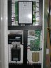
I see no reason why the bottom corners would pose an issue in my cabinet. I didn't take the ducts completely to the bottom because the conduit holes don't quite line up. The ducts on the sides do overlap the cards a bit, so there is some difficulty wiring the first zone of my M1XIN, for example. But since the connectors come off, I just wire it on the connector and slip it in. 1" ducts would not have this issue, but I definitely needed the 1 1/2" for the cat5 for the keypads and between modules. I am actually already getting tight on the ducts around my M1DBH.

Also, I am not sure if you can see it but I have the expansion ring on that cabinet as well. So there is more depth. I had originally intended to put the duct in the leviton expansion ring, and it would have fit, but the face of the cabinet itself would block the ability to get the wire in and out of the duct to the cards.
 
wuench,

That is one of the nicest looking elk installs I have seen. Very professional looking. I should learn from you.
 
I'm not done yet but here is mine so far:

IMG_2099.jpg
 
Thanks Squintz!

Helheim, looks like you and I think a lot alike. I notice a couple of improvements over my setup...

1.) M1G located at the bottom. There is some requirement I read for UL that the battery and power be located as close to the M1 as possible. Yours is a lot closer than mine. I also like to keep power and data as separate as possible which I think your setup does a lot better job at.

2.) The lower cabinet had batteries on the right. My keylock scrapes against my batteries because they are on the left. I was hoping Leviton made an extension ring but apparently they don't for the 14" cabinet. Maybe one of these days i'll get some time and move that stuff around.

Great job.

It is an NEC (NFPA 70) requirement that power limited and non power limited wiring be seperated. The battery leads are not considered power limited becaue of their available current under short circuit or overload. UL reinforces the requirement in their standards.

The beauty of the M1 over most other control units is that they mounted the battery terminals at the bottom of the board closer to where the batteries would be and afar away from all other terminals. Makes instalation a heck of a lot easier but there are other ways for manufacturers and installers to comply.

I still kind of view it as an unrealistic requirement. If you consider things like zone power, bus power, etc going all over the place, why should the main incoming transformer power, need to be separated? Is it because there is no fuse/breaker between the transformer and input power? And if so, then would adding a inline fuse/breaker close to the transformer solve that?
 
It is an NEC (NFPA 70) requirement that power limited and non power limited wiring be seperated. The battery leads are not considered power limited becaue of their available current under short circuit or overload. UL reinforces the requirement in their standards.

The beauty of the M1 over most other control units is that they mounted the battery terminals at the bottom of the board closer to where the batteries would be and afar away from all other terminals. Makes instalation a heck of a lot easier but there are other ways for manufacturers and installers to comply.

So which are power limited and which are non power limited? Can you run the battery leads and main power together?

IMG_1953.jpg

The main power being what? If you are talking 120 Vac then yes you can as long as all of the wires are rated for the highest voltage involved. If you mean the secondary of the Direct Plug in then no unless you provide additional means of seperation such as sleeving on the battery leads.

In all honesty there would probably never be a problem but it is the code.

I have the wires from the transformer to the elk and the battery leads all running through the same 18/4 wire.

By code that is a no no. In reality I have done it myself and never had a problem. I believe there are hundreds of thousands of installations out there like that with no problems. You would have to damage the insulation on both wires to bridge the circuits and them MAYBE you would have a problem.

I would not lose sleep over it.

I am just saying it is code. More and more installations are being inspected. Some AHJ's know their stuff and might catch it.
 
Well since everyone else is showing off here is my M1. Not fully complete yet, but its only missing expanders.

I use slotted duct. All the boards are on standoff's. Custom cable from the M1 to the DO board in the second panel.
The board under the Ethernet interface is a C-Bus interface. The cable to it is a custom made cable as well (half of it anyway).

In the first panel at the bottom right are terminal strips to power the PIR's. I dont like putting multiple calbes in the one terminal so I created a terminal strip with weidmuller terminals (double decker terminals) to distribute the power.

There are 6 boards in total (allowed for) around the house and shed. NO data bus hub used - you dont need one if you design correctly.

The panels are flush mount in the wall. The exposed studs you can see are the cable zoe in the wall. A piece of 9mm thick mdf screw over the top to hide it all away

Mick
 

Attachments

  • M1_Cabinet_1.jpg
    M1_Cabinet_1.jpg
    212.5 KB · Views: 282
  • M1_Cabinet_2.jpg
    M1_Cabinet_2.jpg
    174.7 KB · Views: 197
Am I the only one using the standard Elk cans and mounting hardware?

**EDIT** Picture is low res because I kept getting an "error on page" when trying to upload a JPEG even though the file size was not too big... anybody know what I might be doing wrong?
 

Attachments

  • ELKbox.GIF
    ELKbox.GIF
    628 KB · Views: 400
It depends on alot of factors. Those l;ook fine now, but wait till you try to put all those wires in there. If you don't plan on having covers, thats another factor, but it is near impossible to have all those expanders in there on the glides, wire it neatly and then not crush it closing a cover. It can certainly be done, but I think it is easier, neater and cleaner spreading it out more in a larger can
 
Back
Top