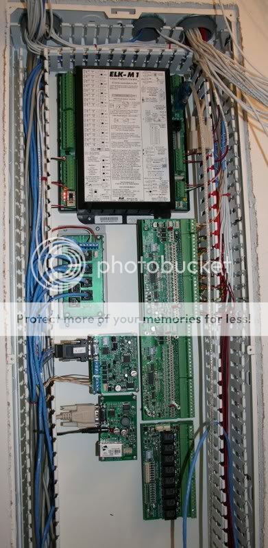
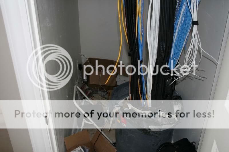
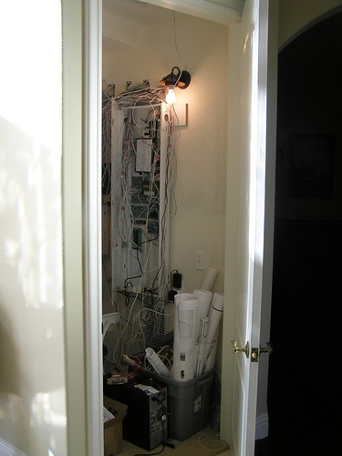
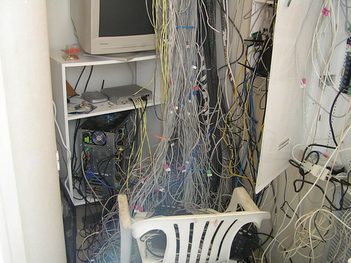
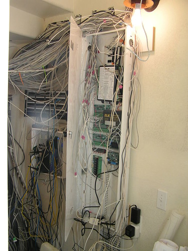
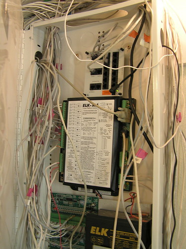
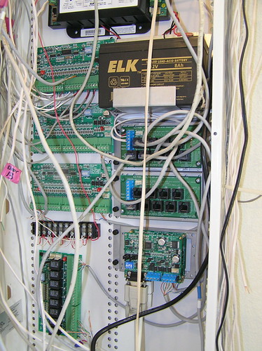
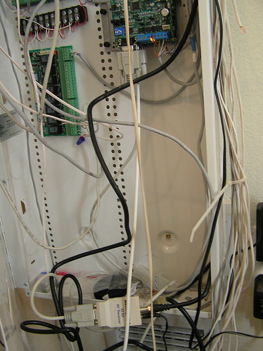
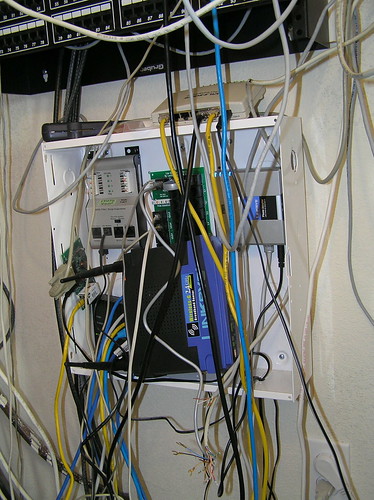
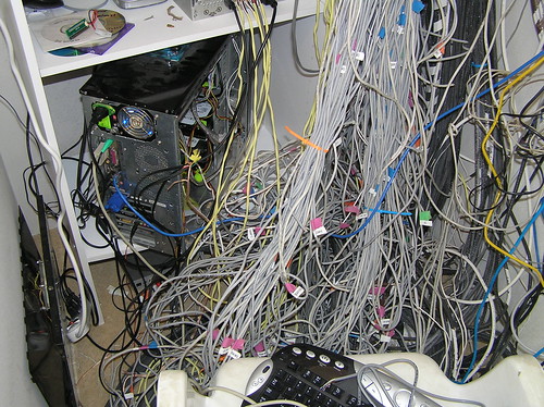
Real neat install! About 5 weeks out now from installing mine, will throw a few pix up then. Modified all my C-Bus cans so each output units has a protected neutral and having a sepearate RCBO on each output unit.
Cheers,
Fleetz
Hi Fleetz
Unless there are local regulations requiring it, there is no advantage to providing protection on the output of the relays and dimmers. The protection wont prevent damage to the triacs either on the dimmers in the event of a short circuit.
This has been discussed a lot on the c-bus forums and the consensus is that it is just a money spending exercise (even though it is covered in the manual).
It does allow isolation of an individual light(s) without the need to isolate the whole dimmer/relay, but in a home situation that is not really an issue. For an office I would contemplate isolation of each channel so others were not disrupted by the outage.
Dont get me wrong, There is nothing wrong with doing it, just that there is little benefit to doing it.
Mick
PS - you will love having c-bus installed. It is a really strong robust system
Hi Mick,
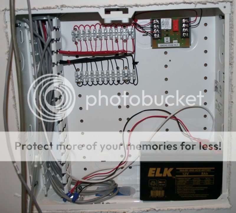
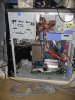
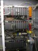
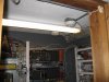
Sorry I might not have explained myself properly. I am refering to having protected neutrals for each output unit not each output. The protected neutral is to enable the RCBO assigned to the output unit (relay or dimmer) to isolate that output unit in the event of any earth leakage on any output connected to that output unit. The thought of having 80 loads with a single RCD and then trying to find which one is the culprit did my head in. So I now have 7 RCBO's for 7 odd output units.
I also have around 70 Rittal lever style disconnect fusable knife switches. These are on each load and whilst I understand that these will not protect each output is gives me an easy way of connecting the the loads and an easy way of isolating any load. Also an easy way of reconfiguring the loads as they are all at the top of the cans. I selected the version that should a fuse go it also illumiated a neon so I can see at a glance which one has gone.
I have probably have over engineered this installation but then it is my paradise home in FNQ!
")
Ping some photos soon.
Regards,
Fleetz