You are using an out of date browser. It may not display this or other websites correctly.
You should upgrade or use an alternative browser.
You should upgrade or use an alternative browser.
Omnipro II, PCAccess, Snap-Link
- Thread starter Phoenix1701
- Start date
-
- Tags
- hai omnipro pc access snaplink

Phoenix1701
Member
pete_c
Guru
The relays / names are defined in the output section and the automation uses the names of the defined relays.
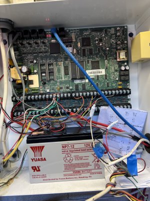
Does this look normal?
yes
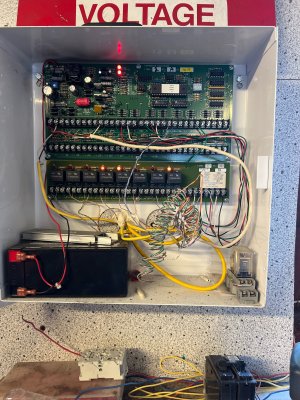
As @McKinneySmart mentions you need to identify wire going to the outputs with a picture.
I posted before seeing the pictures.
note that groups are blocks of programming. You have 41 blocks of programming.
You can copy and paste to notepad one block at a time for automation.
The names of the outputs should match the automation lines.
Make up a little spreadsheet with each board - relay number - device.
For the changes do one output at a time matching the output relays to the name to the automation.
Make sure that the clock is correct on the panel.
Does this look normal?
yes
As @McKinneySmart mentions you need to identify wire going to the outputs with a picture.
I posted before seeing the pictures.
note that groups are blocks of programming. You have 41 blocks of programming.
You can copy and paste to notepad one block at a time for automation.
The names of the outputs should match the automation lines.
Make up a little spreadsheet with each board - relay number - device.
For the changes do one output at a time matching the output relays to the name to the automation.
Make sure that the clock is correct on the panel.
Last edited:
McKinneySmart
Member
Mike,
Thanks for the pictures. Worth '1,000 words'.
Yes, the installation looks normal.
Creating a spreadsheet would be a great step in understanding the mindset of the designer. Plus it would leave documentation for subsequent volunteers.
Good luck.
Thanks for the pictures. Worth '1,000 words'.
Yes, the installation looks normal.
Creating a spreadsheet would be a great step in understanding the mindset of the designer. Plus it would leave documentation for subsequent volunteers.
Good luck.
McKinneySmart
Member
Also, I see cables going to Serial Ports 1 and 2. Do you know what these are for?

Phoenix1701
Member
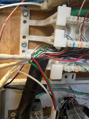
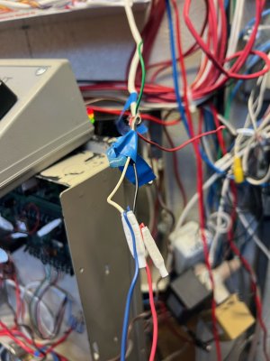
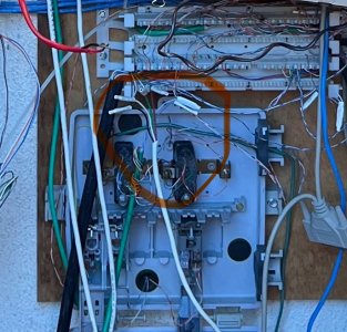
Here is where they both go to. They are just bunded together, not sure what to do with them or how to use them. Also there was a line attached to the data a & b on the board along with the lines going to the keypad and the expansion boxes. It went down to a phone/data block. I currently have it unhooked now. Does it need to be hooked up, and what can be done with it? Will that allow me phone access?
Attachments
pete_c
Guru
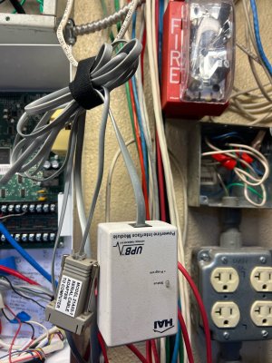
Image2 is a UPB (light switches and maybe modules) controller. This needs to be connected to see your UPB light switches.
That said you can plug this PIM in to a computer running Upstart to see your UPB network.
I do not see what device you have hooked up to second serial port cable.
data a & b on the board along with the lines going to the keypad and the expansion boxes.
These wires would connect to keypads or serial touchscreens or expansion boxes.
These are serial connections. (data RX/TX plus power and ground).
Does it need to be hooked up, and what can be done with it? Will that allow me phone access?
Not sure what you are referring to. I do not see any phone line wires connected in any of the above pictures.
Refer to the manual posted here:
Leviton OmniPro 2 Installation Manual.
So what you want to document is:
1 - zone connections
2 - output connections
3 - UPB Lighting via UPB PIM
to start.....
And connectivity to the Ethernet Port on the panel.
Is there anything written on the inside doors of the main panel and or expansion panels?
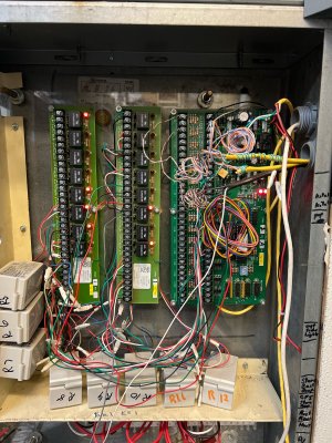
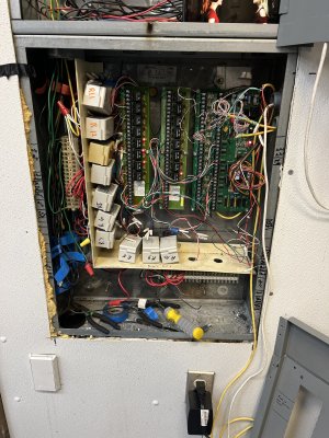
The second / third expansion panels do not have much connected to them.
That said you can plug this PIM in to a computer running Upstart to see your UPB network.
I do not see what device you have hooked up to second serial port cable.
data a & b on the board along with the lines going to the keypad and the expansion boxes.
These wires would connect to keypads or serial touchscreens or expansion boxes.
These are serial connections. (data RX/TX plus power and ground).
Does it need to be hooked up, and what can be done with it? Will that allow me phone access?
Not sure what you are referring to. I do not see any phone line wires connected in any of the above pictures.
Refer to the manual posted here:
Leviton OmniPro 2 Installation Manual.
So what you want to document is:
1 - zone connections
2 - output connections
3 - UPB Lighting via UPB PIM
to start.....
And connectivity to the Ethernet Port on the panel.
Is there anything written on the inside doors of the main panel and or expansion panels?
The second / third expansion panels do not have much connected to them.
Phoenix1701
Member
J1 is the wide flat wire going to the UPB plug that goes into the wall outlet. If we have anything on property that is uses it, I don't know. The J2 cord is what goes to the serial cable adapter. My laptop does not have a serial plug on it so that connection is unusable at the moment.
Next, the line I asked about that was hooked to data a & b, image 1 is the end that was hooked to the board, and image 0 is the end where it goes to that data block. Not sure what that all does yet. Attached is another picture of it before I started rearranging wires. Thats the question on if that was the phone connection. The manuals show something about the system being able to be called into. And I'm still trying to figure out how to get into the system from offsite while at home.
Third, I did a printout from PCAccess. It's 10 pages long and I'm guessing it shows everything related to the system, auto program, what is listed for where. Now in reference to panel 2 & 3 not having much, that's true. 3 years ago the member who was in charge of it, couldn't get it to work so he pulled everything from panel 3. Panel 2 does have 4 relays active out of 9 hooked up in the box. All 3 panels do have 16 items programmed in the energy management. That I believe is what he was planning on future expansion but never got to it before he died. I have also found 3 19A00 boards he got and marked for where here was going to put them.
Fourth, no there is absolutely nothing written down any where about the system. That's what I'm doing and why I'm asking so much and trying to get help. What I've been doing is a lot of trial and error.
Fifth, yes the main board is on the museums network. That is how I've been able to get into the system and see things, and update PCAccess to fix the date problem. That is why I'm asking on how to get into it from remote, phone or web.
Sixth, what I see is following, 3 temperature zones, 56 named outputs for lighting through EE1, EE2, EE3, and main board outputs 1-8, no flags, no user setting, no scene, no phantom, no UPB, no centralite, no HLC, no Z-wave, no thermostat, no message, serial ports are Omni-Link but #3 which is UPB, baud rate 9600, no camera, no hifi2, no music, no rooms, no HAI docks, no codes, no voices. That's what the printout has on it.
Attachments
Last edited:
pete_c
Guru
You can utilize the serial port to the panel via PCA and a USB to serial cable locally.
My laptop does not have a serial plug on it so that connection is unusable at the moment.
And I'm still trying to figure out how to get into the system from offsite while at home.
You can connect to the serial port on the panel via a USB to Serial cable or connector. Works fine with Windows PCA.
Relating to remote access just pass the IP and port (4369) of the panel through the firewall or put the IP of the panel in a DMZ.
or configure OpenVPN on your router and use VPN on your laptop / home computer.
Thats the question on if that was the phone connection. The manuals show something about the system being able to be called into.
The phone connection is typically used with the alarm service and you can call it if configured to give the panel commands. (see manual) but I do not think you can program the panel via that phone line. You can also connect a modem to the serial line but it is easier to go into the panel with PCA (you are already doing this) configuring the firewall to pass the panel info.
If we have anything on property that is uses it, I don't know.
Have a look at the Units configured to see if you had / have any UPB devices configured.
or
Install Upstart on your PC and connect t serial port of the UPB PIM to your PC (via a usb to serial cable) then scan the network.
Can you remove any passwords you have on the print out of the configuration then print it out to a PDF file and post it here.
What do the outputs designated as light relays go to?
Take your time one panel at a time reverse engineering all that has or was done.
Last edited:
Phoenix1701
Member
Here is the new printout from PCA. What is Upstart? Now I understand of getting a USB to serial cable adaptor, then that would connect to the serial plug that is plugged into J2, then plug in the PIM into an outlet which is plugged into J1. Now the laptop is able to see any working PIM's on the property? Sorry everybody, I have so many questions, and also wondering if we should completely replace the systems. I'm trying to look forward and new buildings going up and property being completely done over, basically as if from scratch. Right now we do have, as far as I know, a fully operational Omnipro II motherboard, 3 working expansion boards, and 5 19A00 in use with 3 additional 19A00 boards in packages.
Can I create and build a DMZ from old computers we have on property, or is that something you have to buy?
PCA only allows me access to the system when I'm on the LAN, I can't get into it from off site. I know what the IP address is on the LAN, but not how to get in to it from outside.
Mike
Can I create and build a DMZ from old computers we have on property, or is that something you have to buy?
PCA only allows me access to the system when I'm on the LAN, I can't get into it from off site. I know what the IP address is on the LAN, but not how to get in to it from outside.
Mike
Attachments
Last edited:
pete_c
Guru
Thank you the printout Mike.
PCA only allows me access to the system when I'm on the LAN, I can't get into it from off site. I know what the IP address is on the LAN, but not how to get in to it from outside.
You can leave the IP and port utilized available as you will need that to configure the on site router / firewall to pass the traffic through. You can do this two ways. One is to put the IP of the OmniPro 2 in a DMZ or configure the OmniPro IP / port on the firewall to pass the traffic. You should also update the firmware on the panel to current release. Will post that file here. Have to check if your router / firewall mfg and model. Typically all routers have the ability to make adjustments to the firewall. You do not need to use another computer and or software.
What is Upstart?
Now the laptop is able to see any working PIM's on the property?
Upstart is UPB configuration software. You can connect to the UPB PIM with a PC running Upstart to "map" out and see if you have any UPB devices on site.
wondering if we should completely replace the systems.
Personally the OmniPro 2 panel you have will last forever. That product and the Elk M1 panel are one of a kind devices never replicated.
The panel does well with security, energy management and automation.
Phoenix1701
Member
Thank you Pete. I didn’t see anything on how to update firmware.

Similar threads
- Replies
- 4
- Views
- 304
- Replies
- 3
- Views
- 372
- Replies
- 3
- Views
- 2K
- Replies
- 18
- Views
- 598